Configure Your Network’s Routing
Do you remember the device that acts as a bridge between two networks? This is the router, and its job is to route data, (i.e., direct packets to the right network).
Identify the Steps for Establishing a Path for Messages
To route packets properly, routers have a routing table in their internal memory.
For the table to function, you have to:
Enable the router’s network interfaces.
Configure an IP address for each enabled interface.
Check and modify (if necessary) the routing table.
OK, but what IP address should I configure for the router, seeing as it’s the “bridge” between several networks? I can’t assign several different IP addresses to it, can I?
Actually, yes, you can! A router has as many IP addresses as the number of networks it’s connected to. This means that each physical port or interface has to be configured with an IP address in the right network. Let’s look at a practical example to make this clearer.
Configure Routing for a Simple Architecture
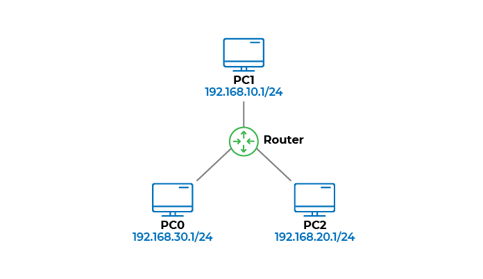
Imagine we’re trying to configure IP addresses for the network interfaces of the routers and PCs in this architecture.
To do this, you first need to determine:
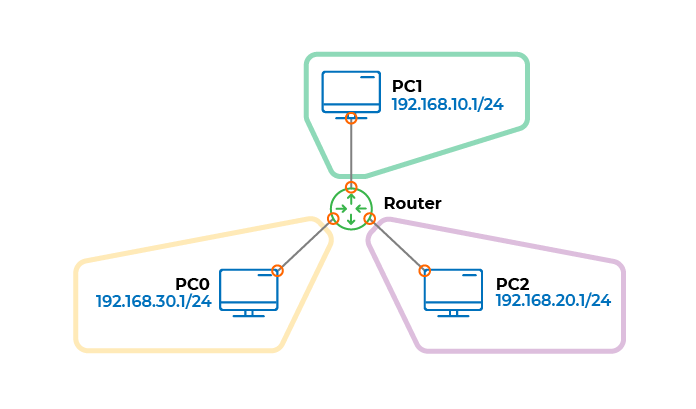
The number of networks in the architecture.
The number of interfaces to configure.
Determine the Number of Networks and Interfaces
For the number of networks, it’s very simple: you know that a router separates the different networks, so you can easily deduce that there are three in this case. For the network interfaces, you know that there is an interface at each end of a cable, so a total of six.
Define the IP Addresses on the Router
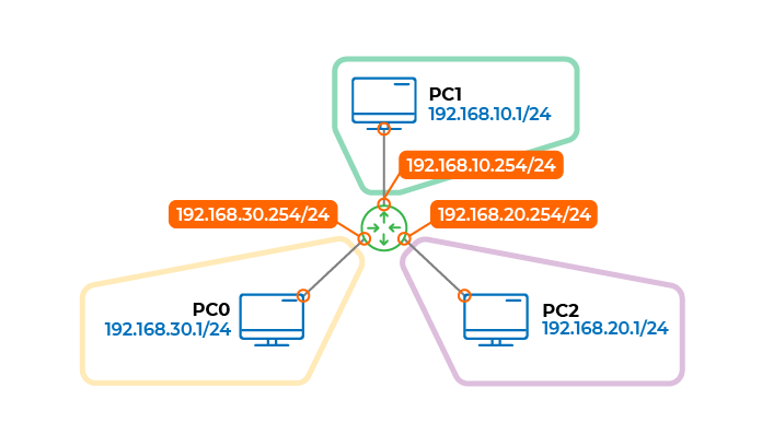
The interfaces of the three PCs already have IP addresses, so you just need to define the IP addresses on the router:
One of the router interfaces is on the same network as PC0. This means that you should assign it an IP address between 192.168.30.2 and 192.168.30.254. Go ahead and take 192.168.30.254/24.
Another of the router interfaces is on the same network as PC1. Following the same logic, you can assign it the IP address 192.168.10.254/24.
As for the last interface, PC2, let’s give it the address 192.168.20.254/24.
Generate a Routing Table
Now let’s take a look at the routing table. You don’t need to create it, as the router itself generates it. This is what it looks like:
Destination network | Network directly connected | Output interface | Next hop |
192.168.10.0/24 | Yes | 192.168.10.254 |
|
192.168.20.0/24 | Yes | 192.168.20.254 |
|
192.168.30.0/24 | Yes | 192.168.30.254 |
|
Don’t worry, we’re going to look into the contents of this table in more detail now!
It has three routes, i.e., three paths to three different networks.
Imagine a packet with a destination address of 192.168.20.1 arrives at the router. The router consults its routing table to see if there is a destination network corresponding to the IP address indicated on the packet. In this case, there is—the network 192.168.20.0/24.
The routing table tells the router that it is directly connected to this network and that to send a packet to the network, it needs to direct it to its interface with the IP address 192.168.20.254.
This is how a router directs packets to the correct network.
I see, but what’s the Next hop column for?
The Next hop column comes in useful for more complex architecture, such as this one, for example:
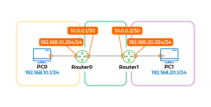
This architecture is made up of two routers and three networks. If you take Router0’s routing table, it would look like this:
Destination network | Network directly connected | Output interface | Next hop |
192.168.10.0/24 | Yes | 192.168.10.254 |
|
10.0.0.0/30 | Yes | 10.0.0.1 |
|
192.168.20.0/24 | No | 10.0.0.1 | 10.0.0.2 |
This table contains three paths to the three networks in the architecture.
This time, if a packet going to 192.168.20.1 arrives at Router0, it sees that the associated network is 192.168.20.0/24. The router is not directly connected to this network—to reach it, it knows that it will have to pass the packet to another router with the address 10.0.0.2. This other router is often identified as the next hop, or gateway in the routing table.
Hmm, all these columns are a bit confusing...
Don’t panic! If you prefer an analogy, think of the next hop as the next border crossing in an itinerary. For example, if you want to go from France to Portugal by road, your next border crossing will be to enter Spain.
Let’s Recap!
A packet must be sent from one IP network to another via a router. This router can also be known as the gateway.
All of the router’s network interfaces must be enabled and have an IP address set in order to route traffic.
The routing table ensures it sends packets to the right destination network. It lists all networks known by the router and the path to take to reach them.
When a router receives a packet, it looks at its destination IP address and compares it with the known networks in its routing table. It then knows where to send the packet.
Now you know how to configure routing for a simple architecture! 🥳 All you need to do now is set a default gateway for your end nodes. Follow me to the next chapter to see how to do this!
