Deploy a Corporate Network
Analyze the Theobald Digital Agency Network Diagram
Right, now we’re going to analyze our corporate case study. Here’s the network diagram of our organization:
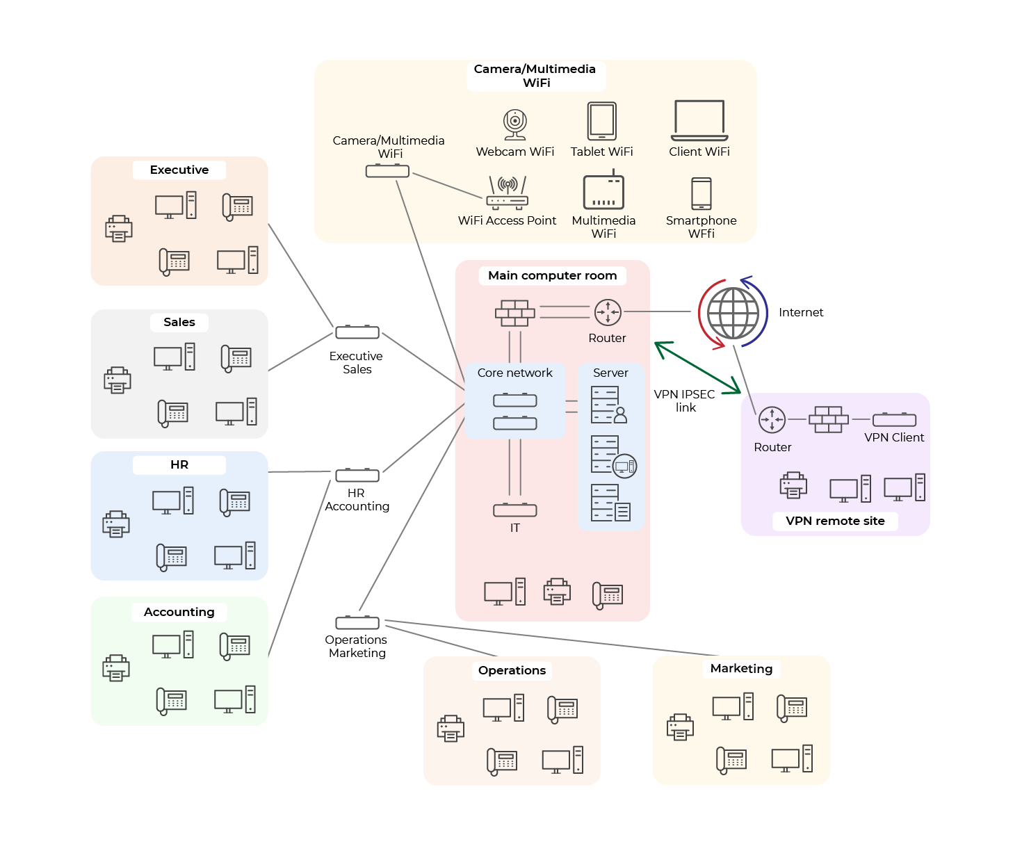
If you analyze this network diagram, you’ll find the following end devices:
Desktop PCs
Laptop PCs
VoIP telephones
Smartphones
Tablets
Printers
Multimedia equipment
IP cameras
Servers
And you’ll also find the following connectivity devices:
Switches
Routers
Firewall
WiFi access points
You need to properly understand the different layers of connectivity devices in the OSI model.
Draw the Corporate Network Diagram
So, now you’ve familiarized yourself with the agency’s network diagram, you're going to draw this diagram in Cisco Packet Tracer.
You're going to start off with a slightly simplified version and add the missing elements as we go through the course. The elements that we’re not going to include initially are:
The remote VPN subnet
The firewall—you’ll connect your networks directly to their respective routers
The WiFi subnet and the IP Camera/Multimedia subnet
A number of switches—there will only be one switch in the core network
VoIP telephones
Why shouldn’t we add the VoIP telephones to the Packet Tracer diagram now?
Well, adding VoIP telephones to an IT network is actually quite complicated. But don’t worry, we’ll get to it later in the course.
However, there are some really important decisions to make:
Which connectivity devices to choose
Which ports to use for the connectivity devices
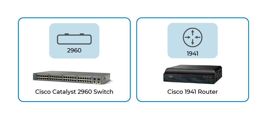
The best thing to do is to take a logical approach. You’re going to use Cisco 2960 switches and Cisco 1941 routers. We’ve chosen these because they are used extensively across the globe by a number of companies. Here are the icons within Cisco Packet Tracer for these connectivity devices, together with their real-life counterparts. Because of course, when you turn up at an organization, it's good to know what a real switch and router actually look like!
Great! Now we need to select which ports we’re going to use. First of all, let’s look at the ports that exist on both the switch and the router:
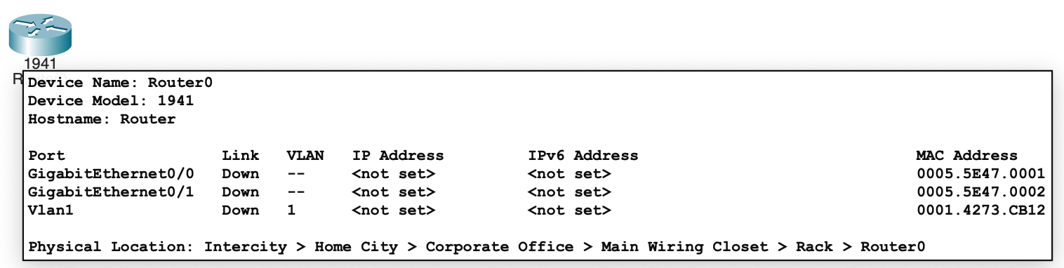
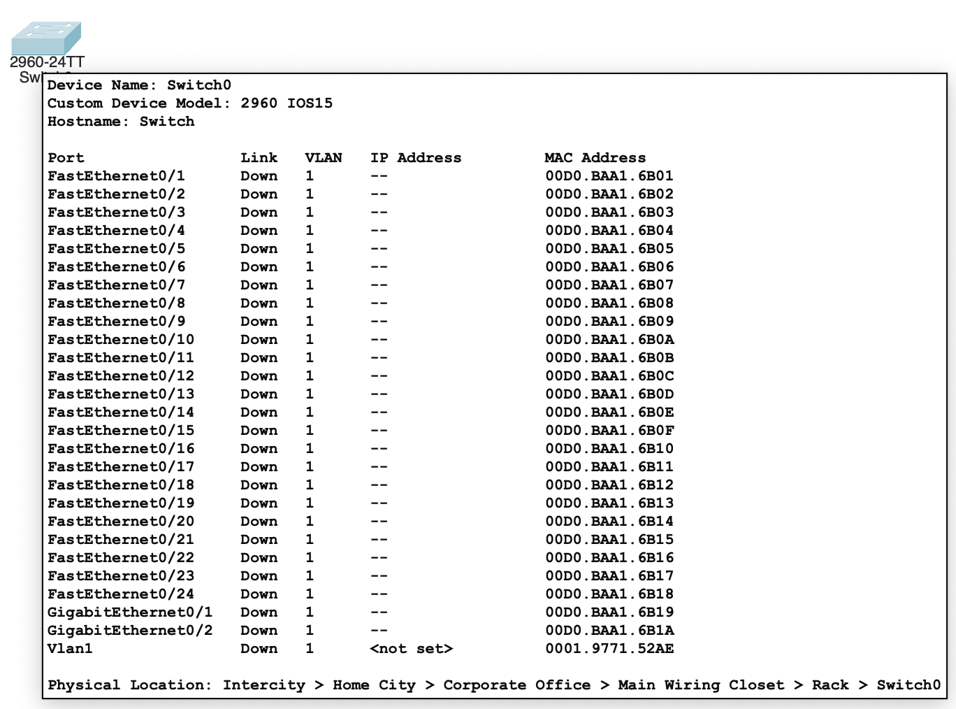
So, to summarize:
The Cisco 1941 router has 2 ports available: GigabitEthernet0/0 and GigabitEthernet0/1.
The Cisco Catalyst 2960 switch has 26 ports available: FastEthernet0/1 to FastEthernet0/24, GigabitEthernet0/1 and GigabitEthernet0/2.
For info, here’s the data throughput information for our devices:
| Router | Switch |
Interface name | GigabitEthernet | FastEthernet |
Theoretical throughput | 1,000 Mb/s (or 1 Gb/s) | 100 Mb/s |
Okay, that’s great! You now know the names of the device interfaces, but these names are quite long to write out. Here’s how we can shorten them:
| Router | Switch |
Interface name | GigabitEthernet0 | FastEthernet0/1 |
Short interface name | g0/0 | f0/1 |
Right, now we need to choose which ports to use on the switches. One thing to note is that all connections to your core network must be GigabitEthernet.
Argh, nightmare! Why’s that?
Well, if you use a Cisco Catalyst 2960 for the core network, you only have 2 Gigabit Ethernet ports available. Some connections will be GigabitEthernet and others will be FastEthernet!
It’s okay, there’s a solution to this problem. Let’s see what other devices you have available in Cisco Packet Tracer. Ah, here we are! This switch looks like it will do the job, the Cisco Catalyst 3650:
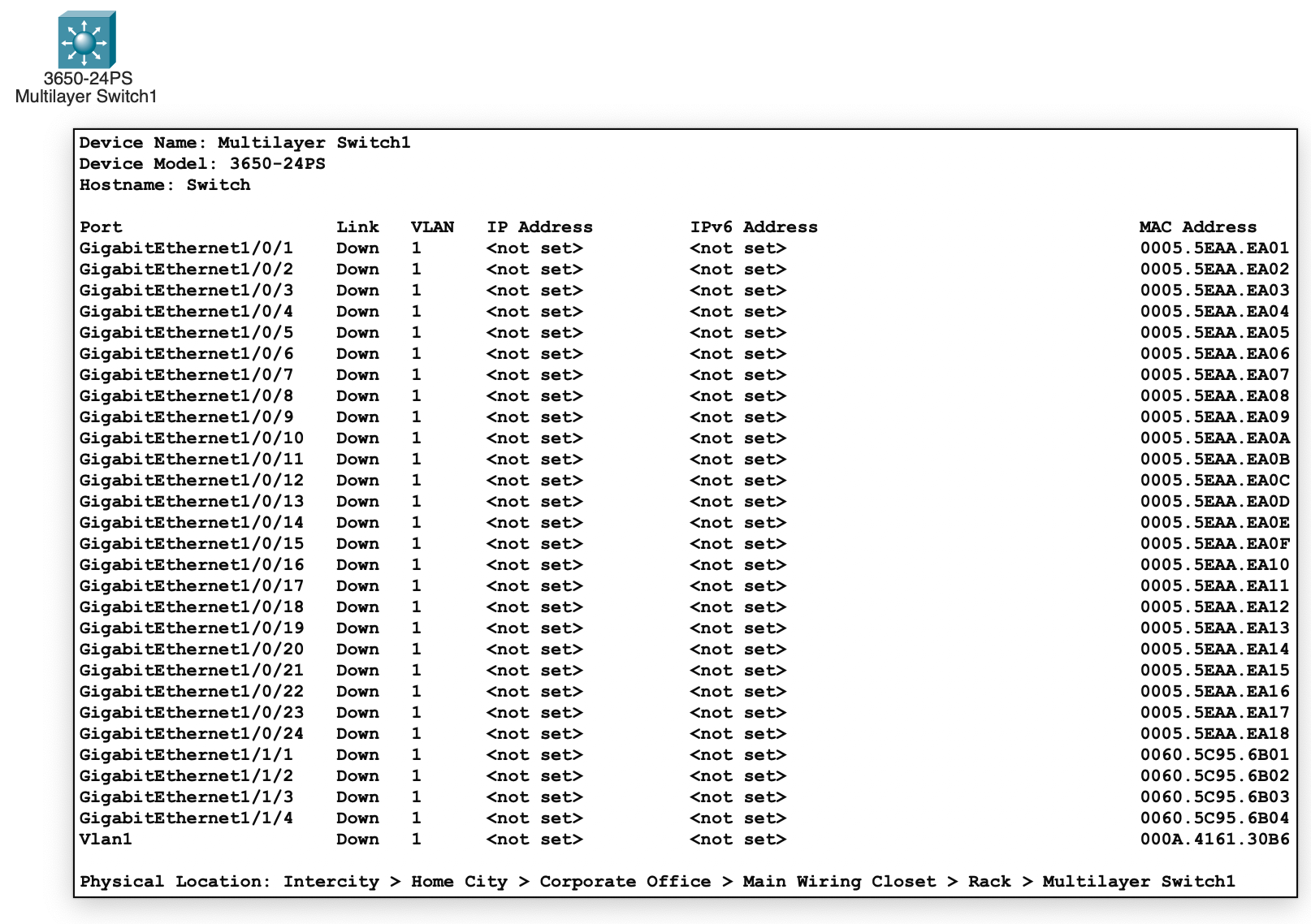
Wow, that’s a powerful switch!
28 GigabitEthernet ports! In actual fact, there are 24 GigabitEthernet ports and four 10GigabitEthernet ports!
Okay, so now we’ll define exactly which interfaces we’re going to use. Let’s use this simplified network diagram:
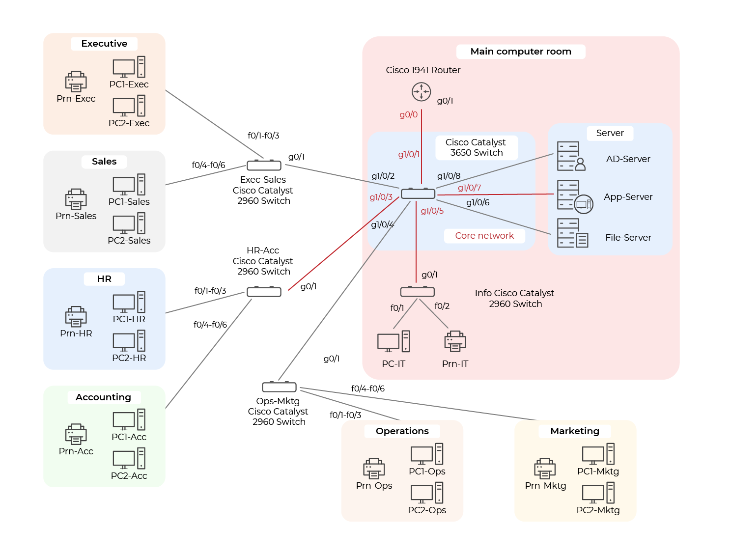
We’re going to use the following convention for the interfaces we’re using for the various subnets:
PC1: first available interface
PC2: second available interface
Prn: third available interface
For example, for the Exec-Sales Cisco Catalyst 2960 switch, we’ll connect the interfaces as follows:
Interface | Connected to |
f0/1 | PC1-Exec |
f0/2 | PC2-Exec |
f0/3 | Prn-Exec |
f0/4 | PC1-Sales |
f0/5 | PC2-Sales |
f0/6 | Prn-Sales |
Right, off you go! Start drawing the network diagram in Cisco Packet Tracer.
Let's Recap!
In this chapter, you’ve seen:
how to choose and name the interfaces for a Cisco network device.
the theoretical throughput provided by the different interfaces on a connectivity device:
FastEthernet: 100 Mb/s
GigabitEthernet: 1Gb/s.
how to deploy a corporate network using Cisco Packet Tracer.
Now that you've created the network diagram, you're going to configure the IP parameters in Cisco Packet Tracer.
