Learn How a Layer 2 Switch Operates
Discover How a Switch Operates When Setting up a Network
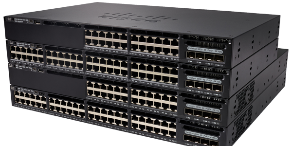
As you’ve seen previously, a switch allows end devices to be connected to each other. Let’s take a look at switches in a little more detail.
The notion of switching and frame transmission (or encapsulation) is universal in network and telecommunication. The concept applies to different types of switches in LAN, WAN, and telephone networks.
The decision a switch makes about how to transmit the network traffic is based on the flow of traffic. There are two terms used for frames that enter and exit an interface:
Entry (Ingress): This is used to describe the port used by a packet to enter the device.
Exit (Egress): This is used to describe the port used by a packet to exit the device.
A LAN switch holds a table that is referred to when the switch is processing traffic. The only intelligent part of a LAN switch is the way it uses the table to transfer the traffic.
A LAN switch transmits traffic based on the port of ingress and the destination MAC address of an Ethernet frame. With a LAN switch, there is just one master switching table that defines a strict association between MAC addresses and ports.
This means that an Ethernet frame with a given destination address always exits from the same egress port regardless of which ingress port it used to enter the device.
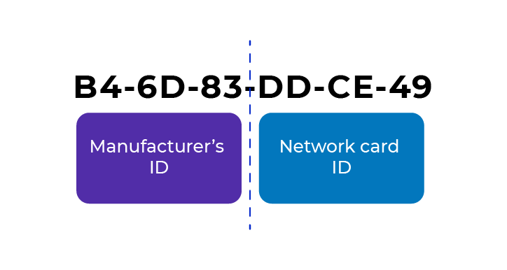
As a reminder, a MAC address is a unique physical identifier for each network card and consists of 12 hexadecimal characters.
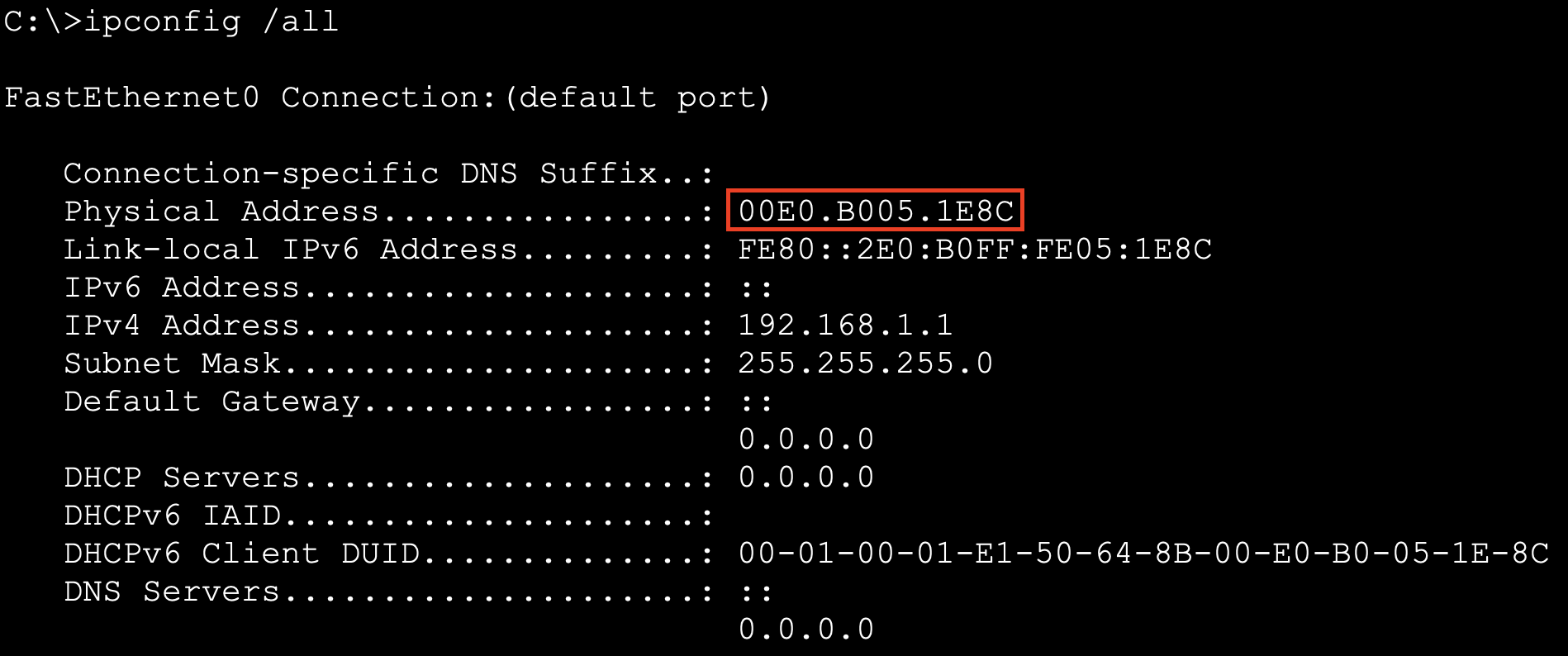
To display the MAC address of your Windows workstation, type the command ipconfig /all in command prompt.
Define the MAC Address Table in the Switch
Switches use the destination MAC address. This is how they direct network communications.
A switch needs to know which devices exist on each port before it can decide which port to use to forward a frame.
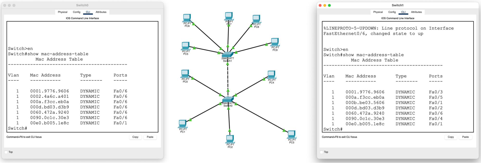
As it learns about the relationships between ports and devices, it builds a table called a MAC address table. This table is held in the CAM (Content Addressable Memory). It’s a particular type of memory used in high-speed search applications. For this reason, the MAC address table is also known as the CAM table. You can display the Exec-Sales switch’s CAM table using the command show mac-address-table:
Switch# show mac-address-table
     Mac Address Table
 -------------------------------------------

Vlan Mac Address   Type   Ports
---- -----------   --------  -----

Switch#
The CAM table needs some communications to be initiated before it can start to build entries. For example, by pinging PC1-Exec and PC2-Exec workstations:
Switch# show mac-address-table
     Mac Address Table
-------------------------------------------

Vlan Mac Address   Type   Ports
---- -----------   -------- -----

   1 0010.11ec.9e37 DYNAMICFa0/2
   1 00d0.97be.a596 DYNAMICFa0/1

Switch#We could make a little summary table of the CAM table, as follows:
Destination address | Port |
00-D0-97-BE-A5-96 | Fa0/1 |
00-10-11-EC-9E-37 | Fa0/2 |
Adopt the “Switch Learning and Forwarding” Method
The following process consists of two steps and is carried out on each Ethernet frame that enters a switch.
Step 1. Discovery Mode: Examine the Source MAC Address
The switch verifies if any new data is available on each of the incoming frames. It does this by examining the source MAC address of the frame and the port number the frame used to enter the switch.
If the source MAC address doesn’t exist in the MAC address table, the MAC address and the inbound port number are added to the table.
If the source MAC address exists, the switch resets the refresh timer for this entry. By default, most Ethernet switches retain the table entries for 5 minutes.
If the source MAC address exists in the table for a different port, the switch will treat it as a new entry. The entry is replaced using the same MAC address but with the most recent port number.
Step 2. Forwarding: Examine the Destination MAC Address
If the MAC address is a unicast transmission address, the switch will look for a link between the frame’s destination MAC address and an entry in its MAC address table.
If the destination MAC address exists in the table, the switch forwards the frame using the specified port.
If the destination MAC address doesn't exist in the table, the switch forwards the frame using all ports except for the port of entry. This is called an unknown unicast.
If the destination MAC address is a broadcast or multicast, the frame is also sent via all ports except for the port of entry.
Use the Broadcast Method for the Switch
Switches make decisions about layer 2 transfers very quickly. This is due to the Application-Specific Integrated Circuits (ASICs). ASICs reduce the image processing time within the device and allow it to manage a high volume of images without impacting on performance.
Layer 2 switches use one of the following methods for changing frame:
Store and forward switching: This method decides on how to broadcast a frame. After receiving the whole frame, the method checks for any errors in the frame using a mathematical error-checking mechanism. We call this the cyclic redundancy check (CRC). Store and forward switching is Cisco's main LAN switching method.
Cut-through switching: This method launches the transfer process after first determining the MAC address of the incoming frame and its exit port.
Let's Recap!
In this chapter, you’ve seen:
how the switch uses a MAC address table so that it knows which port to use when forwarding a frame.
how the MAC address table links a MAC address with a port and how a port can handle many MAC addresses.
how a MAC address table is:
populated using the source MAC addresses of the devices on each port.
used by analyzing the destination MAC addresses of frames arriving at the ports and comparing them to the MAC addresses already present in the CAM (Content Addressable Memory) table.
how switches use two methods to change frames using Application-Specific Integrated Circuits (ASICs).
how store and forward checks if the frame contains any errors using a CRC.
how cut-through transfers the frame as soon as it has determined the destination MAC address and the exit port.
Now that you understand how a switch works, I’m going to introduce you to the command line interface (CLI) in the next chapter.
