Configure Basic Parameters in a Layer 2 Switch
Configure the SVI of Your Layer 2 Switch
Now that you know how to use the CLI in Cisco Packet Tracer, the first thing you’re going to do is configure the basic parameters for a layer 2 switch.
To access the switch remotely, you need to configure an IP address and a subnet mask in the SVI (Switch Virtual Interface).
What is an SVI?
Layer 2 switches, such as the Cisco Catalyst 2960, have physical ports to which devices can be connected. But these physical ports can't handle layer 3 IP addresses. As a result, switches have one or more virtual switch interfaces.
These interfaces are virtual because there is no hardware on the associated device. This SVI (virtual interface) is created within the software. The virtual interface is a way of remotely managing a switch on a network using IPv4 or IPv6. Every switch has a ready-to-use SVI provided within its default configuration. This SVI is within the default VLAN1.
What is a VLAN?
In part four, you’ll find out more details about VLANs, but for now, you just need to remember that a VLAN is an independent network created inside a switch.
By default, the switch is configured so that:
its management is controlled by VLAN1.
all ports are assigned to VLAN1.
Switch# show vlan brief
VLAN        Name             Status       Ports
----  --------------- ----------   --------------------
1      default               active   Fa0/1, Fa0/2, Fa0/3,
Fa0/4
                                     Fa0/5, Fa0/6, Fa0/7,
Fa0/8
                                     Fa0/9, Fa0/10, Fa0/11,
Fa0/12
                                     Fa0/13, Fa0/14, Fa0/15,
Fa0/16
                                     Fa0/17, Fa0/18, Fa0/19,
Fa0/20
                                     Fa0/21, Fa0/22, Fa0/23,
Fa0/24
                                     Gig0/1, Gig0/2
1002   fddi-default           active
1003   token-ring-default     active
1004   fddinet-default        active
1005   trnet-default          active
Switch#
In privileged EXEC mode, type theshow vlan briefcommand to display the assigned VLANs within the ports.
For security reasons, it is good practice to use a different VLAN than VLAN1 to manage the VLAN. Have a look at the addressing plan:
Groups | VLAN ID | Network address | First available address | Last available address |
Network devices | 10 | 192.168.10.0/24 | 192.168.10.1 | 192.168.10.253 |
Administration | 100 | 192.168.100.0/24 | 192.168.100.1 | 192.168.100.253 |
Groups | Network gateway |
Network devices | 192.168.10.1 |
Administration | 192.168.100.254 |
We can see two VLANs for managing network devices:
The first VLAN (Network devices – ID 10) is a VLAN connecting the layer 3 switch to the internet router.
The second VLAN (Administration – ID 100) enables the network devices to be configured. This is the one we’re interested in.
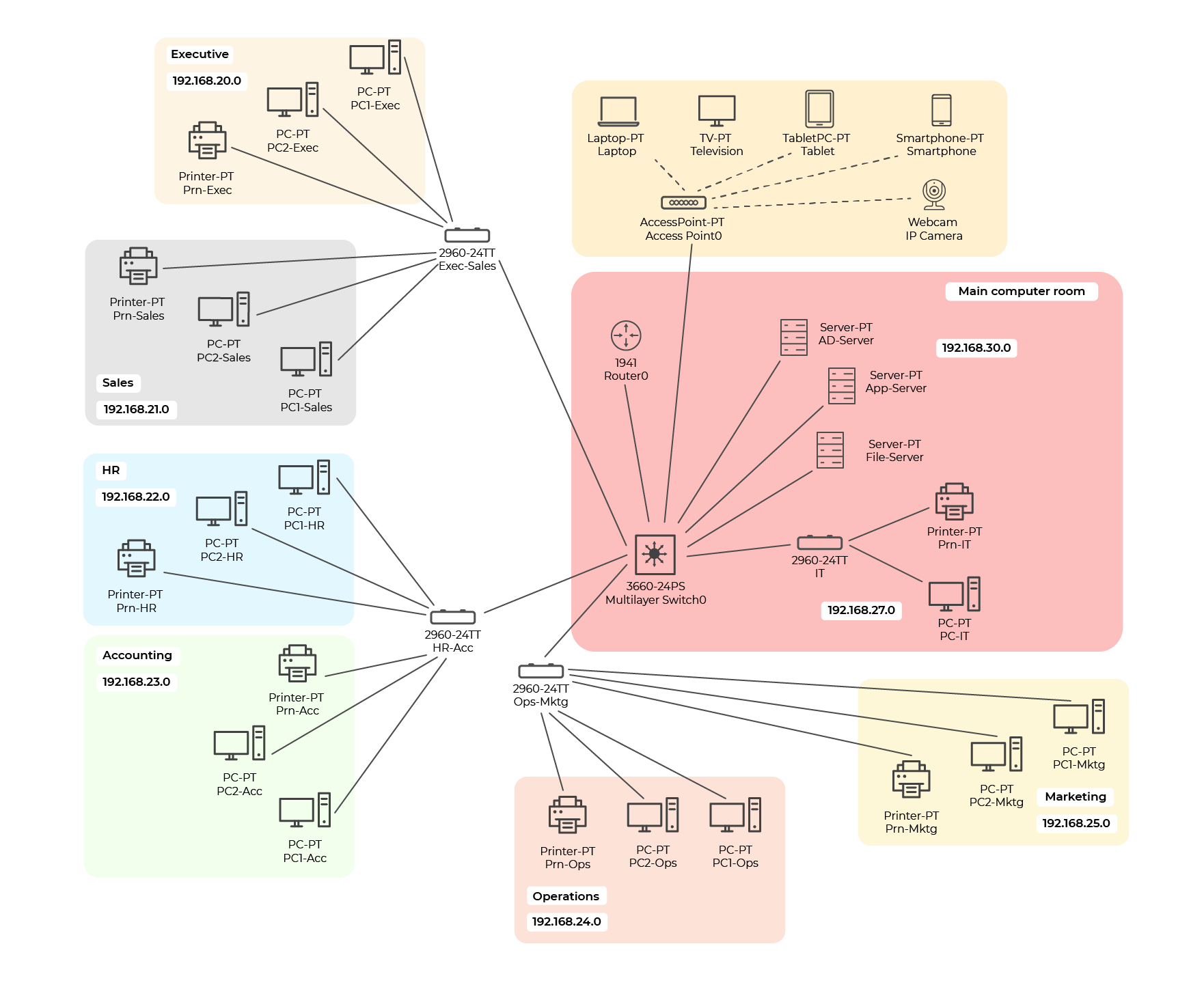
So, you have three Cisco Catalyst 2960 switches, one Cisco Catalyst 3650 switch and one WiFi access point.
Take this addressing plan for the switches and add the IPv6:
| IPv4 Address | IPv6 Address |
Switch Cisco Catalyst 3650 | 192.168.100.1/24 | 2001:db8:acad:100::1/64 |
Switch Exec-Sales | 192.168.100.2/24 | 2001:db8:acad:100::2/64 |
Switch HR-Acc | 192.168.100.3/24 | 2001:db8:acad:100::3/64 |
Switch Ops-Mktg | 192.168.100.4/24 | 2001:db8:acad:100::4/64 |
Switch IT | 192.168.100.5/24 | 2001:db8:acad:100::5/64 |
Network gateway | 192.168.100.254 | 2001:db8:acad:100::254/64 |
To configure the Exec-Sales Cisco Catalyst switch, you need to follow these steps precisely:
Switch(config)# hostname Exec-Sales
Exec-Sales(config)# interface vlan 100
Exec-Sales(config-if)# ip address 192.168.100.2 255.255.255.0
Exec-Sales(config-if)# ipv6 address 2001:db8:acad:100::2/64
Exec-Sales(config-if)# no shutdown
Here’s a short video where we’ll configure the management interface together:
Configure the Default Gateway
Now, you're going to configure a default gateway on your switches.
To configure the default gateway for the Exec-Sales Cisco Catalyst switch so that it can be managed remotely, follow the steps below:
Exec-Sales(config)# ip default-gateway 192.168.100.254
Here’s a short video where we’ll configure the default gateway together:
Check the Basic Configuration Parameters of a Cisco Catalyst 2960 Switch
To check the configuration of your layer 2 switches, we’re going to use theshow ip interface briefandshow ipv6 interface briefcommands to determine the status of the physical and virtual interfaces.
Here’s what you’ll see after using theshow ip interface briefcommand:
Switch# show ip interface brief
Interface          IP-Address   OK? Method Status
Protocol
FastEthernet0/1     unassigned   YES manual down
    down
FastEthernet0/2     unassigned   YES manual down
   down
FastEthernet0/3     unassigned   YES manual down
   down
FastEthernet0/4     unassigned   YES manual down
   down
FastEthernet0/5     unassigned   YES manual down
   down
FastEthernet0/6     unassigned   YES manual down
   down
FastEthernet0/7     unassigned   YES manual down
   down
FastEthernet0/8     unassigned   YES manual down
   down
FastEthernet0/9     unassigned   YES manual down
   down
FastEthernet0/10    unassigned   YES manual down
   down
FastEthernet0/11    unassigned   YES manual down
   down
FastEthernet0/12    unassigned   YES manual down
   down
 FastEthernet0/13   unassigned   YES manual down
   down
FastEthernet0/14    unassigned   YES manual down
   down
FastEthernet0/15    unassigned   YES manual down
   down
FastEthernet0/16    unassigned   YES manual down
   down
FastEthernet0/17    unassigned   YES manual down
   down
FastEthernet0/18    unassigned   YES manual down
   down
FastEthernet0/19    unassigned   YES manual down
   down
FastEthernet0/20    unassigned   YES manual down
   down
FastEthernet0/21    unassigned   YES manual down
   down
FastEthernet0/22    unassigned   YES manual down
   down
FastEthernet0/23    unassigned   YES manual down
   down
FastEthernet0/24    unassigned   YES manual down
   down
GigabitEthernet0/1  unassigned   YES manual down
   down
GigabitEthernet0/2  unassigned   YES manual down
   down
Vlan1               unassigned   YES manual
administratively dow  down
Switch#
And here’s the result when you use theshow ipv6 interface briefcommand:
Switch# show ipv6 interface brief
FastEthernet0/1     [down/down]
FastEthernet0/2     [down/down]
FastEthernet0/3     [down/down]
FastEthernet0/4     [down/down]
FastEthernet0/5     [down/down]
FastEthernet0/6     [down/down]
FastEthernet0/7     [down/down]
FastEthernet0/8     [down/down]
FastEthernet0/9     [down/down]
FastEthernet0/10     [down/down]
FastEthernet0/11    [down/down]
FastEthernet0/12     [down/down]
FastEthernet0/13     [down/down]
FastEthernet0/14     [down/down]
FastEthernet0/15     [down/down]
FastEthernet0/16     [down/down]
FastEthernet0/17     [down/down]
FastEthernet0/18     [down/down]
FastEthernet0/19     [down/down]
FastEthernet0/20     [down/down]
FastEthernet0/21     [down/down]
FastEthernet0/22     [down/down]
FastEthernet0/23     [down/down]
FastEthernet0/24     [down/down]
GigabitEthernet0/1    [down/down]
GigabitEthernet0/2     [down/down]
Vlan1          [administratively down/down]
unassigned
Switch#
Right, here's a new video showing how to check the configuration.
Let's Recap!
In this chapter, you’ve seen:
how to configure the management interface of a Cisco switch.
how to configure the default gateway in a Cisco switch.
how to configure SSH access in a Cisco switch.
Now that you know how to configure the basic parameters of a layer 2 switch, you’re going to tackle SSH access configuration on your Cisco switch.
