Configure the Routing on Your Router
Understand How a Router Works
To prevent a router from transferring a packet just anywhere, the router must determine the best path (route) for the packet it’s handling. Unlike a switch (except for layer 3 switches, which behave like routers), a router links a number of networks together. It has several interfaces, each belonging to a different subnet.
When a router receives a packet on an interface, it determines which interface it needs to use to transfer the packet to its destination. The interface used by the router to transfer the packet might be:
the final destination (we call this an edge router).
a network connected to another router used to reach the destination router.
The best route in the routing table will be the longest link. So, you just need to take the longest prefix:
Route entry points | Length of prefix | Address in binary notation |
1 | 172.16.0.0/12 | 10101100.00010000.00000000.00001010 |
2 | 172.16.0.0/18 | 10101100.00010000.00000000.00001010 |
3 | 172.16.0.0/26 | 10101100.00010000.00000000.00001010 |
It’s the same principle for IPv6 routes. If a packet arrives at 2001:db8:c000::99, the routing table of the router will look like this:
Route entry points | Length of prefix | Connection |
1 | 2001:db8:c000::/40 | 40 bits |
2 | 2001:db8:c000::/48 | 48 bits |
3 | 2001:db8:c000:5555::/64 | Although it’s 64 bits, it doesn't count because of the subnet |
Routing tables can be completed in several ways:
Directly connected networks are networks configured on the router’s active interfaces. A directly connected network is added to the routing table when an interface is configured with an IP address and a subnet mask (length of prefix) and when it’s active (up).
Remote networks are networks that are not directly connected to the router. The router learns about remote networks in two different ways:
Static routes: Added to the routing table when a route is configured manually.
Dynamic routing protocols: Added to the routing table when the protocols are learned dynamically on the remote network. Dynamic routing protocols include OSPF (Open Shortest Path First) and EIGRP (Enhanced Interior Gateway Routing Protocol), amongst others.
A default route specifies a next hop router that is used when the routing table doesn’t contain a specific route for the destination IP address. The default route can be entered manually as a static route or automatically learned using a dynamic routing protocol.
Configure the Routes for Your Router
Now you know how routers work, you’re going to configure the routing tables for your routers. I’ve created a diagram of our three routers to help you.
Three routers?
Well yes, remember you have a layer 3 switch, which acts as a router:
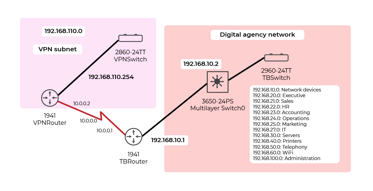
So, you have three routing tables to complete, and we’re going to do it manually.
Here’s how you're going to complete them. Let’s start with the routing table for the VPN router:
Destination network | Subnet mask | Gateway |
0.0.0.0 | 0.0.0.0 | 10.0.0.1 |
Wow, that’s so simple!
Well, yes. You’ve used a default route because your router is located at the network edge. So, if you want to go somewhere other than your subnet (192.168.110.0/24), you have to pass through the gateway at the IP address 10.0.0.1.
You’ll also notice that you don’t need to specify any directly connected networks, because the router already knows about these.
Right, I’ll show you how to configure a default route. You just need to type the following command:
VPNRouter(config)# ip route 0.0.0.0 0.0.0.0 10.0.0.1
So that’s all good, but you're going to take it a step further by configuring a IPv6 routing table. Don't worry, I’ll show you how to do it. But first of all, you need to enable IPv6 routing and specify the default route.
VPNRouter(config)# ipv6 unicast-routing
VPNRouter(config)# ipv6 route ::/0 2001:db8:acad:1001::1
The only difference when using ipv6 rather than ip is the format of the default route: ::/0.
I’ll show you this configuration in this video:
Right, now you're going to configure the organization’s router and it’s (a tiny bit) more complicated because it’s not an edge router. You’ll need to specify a number of routes.
So, I’ll leave you to work out what the routing table for the agency’s router will look like.
Have you finished? (In IPv4, of course):
Destination network | Subnet mask | Gateway |
192.168.110.0 | 255.255.255.0 | 10.0.0.2 |
0.0.0.0 | 0.0.0.0 | 192.168.10.2 |
Easy, isn't it? By using a default route, you just need to add the remote network and that’s it!
Right, here are the commands for the configuration:
TBRouter(config)# ip route 192.168.110.0 255.255.255.0 10.0.0.2
TBRouter(config)# ip route 0.0.0.0 0.0.0.0 192.168.10.2
TBRouter(config)# ipv6 unicast-routing
TBRouter(config)# ipv6 route 2001:db8:acad:110::0/64
2001:db8:acad:1001::2
TBRouter(config)# ipv6 route ::/0 2001:db8:acad:10::2
Right, now you need to configure the layer 3 switch. You haven't even touched it yet! For info, you need to use the following three steps to configure a router (or a layer 3 switch) properly:
Provide a host name
Configure interfaces
Configure the routing table
I’ve adapted the previous diagram and added the interface names to help you:
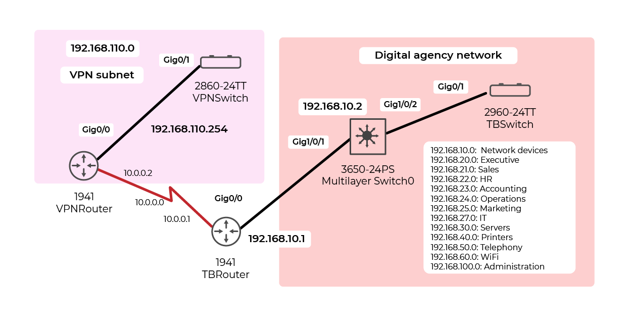
We could quite rightly consider a layer 3 switch to be an edge router, because it’s located at the edge of the network. Routing between the different subnets within the organization is provided by inter-VLAN routing.
This means that the routing table for the layer 3 switch will be quite simple:
Destination network | Subnet mask | Gateway |
0.0.0.0 | 0.0.0.0 | 192.168.10.1 |
Here are the commands to enter for the layer 3 switch (the ip routing command enables IPv4 routing on a layer 3 switch):
Switch(config)# hostname SwitchL3
SwitchL3(config)# interface g1/0/1
SwitchL3(config-if)# no switchport
SwitchL3(config-if)# ip address 192.168.10.2 255.255.255.0
SwitchL3(config-if)# ipv6 address 2001:db8:acad:10::2/64
SwitchL3(config-if)# exit SwitchL3(config)# ip routing
SwitchL3(config)# ip route 0.0.0.0 0.0.0.0 192.168.10.1
SwitchL3(config)# ipv6 unicast-routing
SwitchL3(config)# ipv6 route ::/0 2001:db8:acad:10::1
Here’s a little video to explain this configuration:
Let's Recap!
In this chapter, you’ve seen:
how a router selects the best route to get a packet to its final destination using a routing table.
how to configure and display the routing table for a router.
Now you know how to configure a router, you’re going to check that it’s working correctly in the next chapter.
