Formalize Your Domain Model With a Use Case Diagram
Sometimes pictures can tell a story better than words. Here’s a picture for you. What is it?
This image represents a user, or actor, of a system. As mentioned in the first part of this course, you capture the domain model in many forms. In this section, we will look at some formal documentation approaches for doing that. In particular, you will learn to generate a use case diagram, which is a type of UML model.
What is UML?
UML stands for the Unified Modeling Language. It’s a standard notation that you can use to model, or visually represent software systems. Years ago, there were many ideas on how to represent a system. Everyone had their way of doing it. Some used circles, others rectangles, some dashed clouds. It was tough to keep all these approaches straight. Eventually, an agreement was reached on what images should be used for which modeling ideas (like the actor stick figure). That’s what the Unified part of Unified Modeling Language means.
With the information you've gathered so far, you can construct one type of UML diagram: the use case diagram. It's a way to capture what your system can do, in picture form, for various users. It will represent the work you did earlier to capture system users and what they want the system to do. This is a diagram you generate early in the process and keep up to date as you learn more about what the user wants.
Designing a Use Case Diagram
Let’s put one of those use case diagrams together. We'll build it following these steps:
Identify the actors.
Define the use cases.
Add relationships.
It's as easy as one, two, three! 😉
Step 1: Identify the Actors
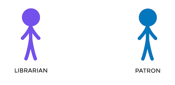
You’ve seen the first item that appears on the diagram in the introduction to this chapter: the actors! Actors are shown as stick figures, with a quick description of the type of user they are (their role) underneath. Let's go back to the example of the library application and create the diagram by adding the actors you've discovered who will use the system.
Ok, great! Now, on to defining the goals of the actors.
Step 2: Identify the Use Cases
Let’s give the users something to do: use cases. You get them by reviewing the conversations you had with the librarians and patrons. Show a use case as an oval, with the goal written inside. The goal is typically described as some result from the user's perspective, not the system's. For example, you would write "Check-in book" (that's what the librarian wants to do) rather than "Update book status in the database record," or "Database book record updated." (That's how the system will do it.) Right now, you aren't concerned with how this will get done, just that the user wants it to do.
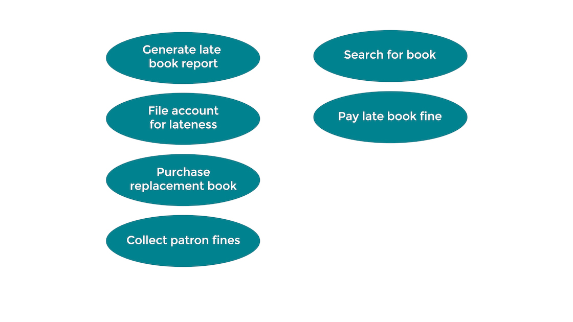
You can see in the image above that use cases for librarians are on the right, and use cases for patrons are on the left. Ok, you've got your use cases, but how are you going to connect them to your actors? With relationships, of course!
Step 3: Add Relationships
Now you need to show which actors are interested in achieving which goal(s). Do that with a connecting line (called a relationship).
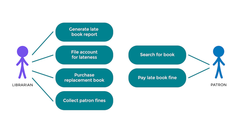
It’s that simple. Add stick figures to your diagram as you discover new types of users. Add more ovals and connections as you discover new functionality the users want. There are two users in the above diagram, each with separate goals. This is an early indicator that you probably have two domains or at least two subdomains in our system.
Sometimes, when you dig deeper into the actual implementation of use cases, you notice that there are duplicate steps among the various cases. For example, there may be several use cases that have "then send an email to someone" as part of their execution. It can be handy to see this shared activity visually. You can indicate dependency with arrows. In this case, "Fine accounts for lateness" depends on "Send email" doing some of the work. And there would be more dashed arrows pointing to "Send email" coming from other use cases.
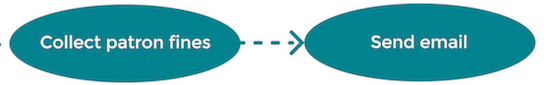
Earlier, it appeared as though there were two subdomains (librarian and patron), but that doesn't mean they don't interact. If you look at the diagram, you see that there is some connection between "Pay late book fine" and "Collect patron fines." It's too early to know how those two use cases will interact with one another, but you can indicate that they will:
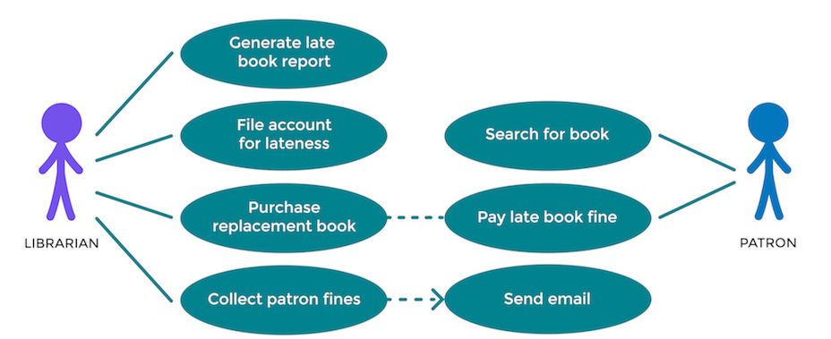
Finally, you will end up with a diagram showing actors, use cases, and the relationships between all of them.
What do I do with these diagrams?
You will expand the goals, capturing the system responses to user inputs in text form. (You'll see how to do that in the next chapter.) You can then examine these text descriptions to determine what classes and objects need to exist. Simple use case diagrams like these are a great way to communicate with users about what they want to achieve.
Let's Recap!
Use case diagrams capture the goals of users in picture form. It shows the relationship between actors and use cases, actors and actors, and use cases and use cases.
Use case diagrams are often drawn using UML.
Actors are shown as stick figures.
Use cases are shown as ovals, with a goal written inside.
As we've said, there isn't any detail here, but it gives you a great starting point. 🙂
In the next chapter, we will take individual use cases and expand them into a description of user interactions with the system.
