Add a Wireless Access Point to the Agency’s Network
Select Your Wireless Access Point
Now you're going to move on to wireless devices and add some wireless end devices to your network diagram in Packet Tracer:
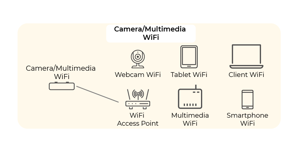
Let’s look back at our IP addressing plan. This is what it looked like for the WiFi and communication equipment:
Groups | VLAN ID | Network address | First available address | Last available address | Network gateway |
WIFI | 60 | 192.168.60.0/24 | 192.168.60.1 | 192.168.60.253 | 192.168.60.254 |
Camera /Multimedia | 90 | 192.168.90.0/24 | 192.168.90.1 | 192.168.90.253 | 192.168.90.254 |
To keep things simple and readable, I suggest that we merge these two networks and just retain one of them: WiFi 192.168.60.0/24.
Have a look at the wireless devices that are available in Cisco Packet Tracer by going to the Network Devices menu and choosing Wireless Devices:
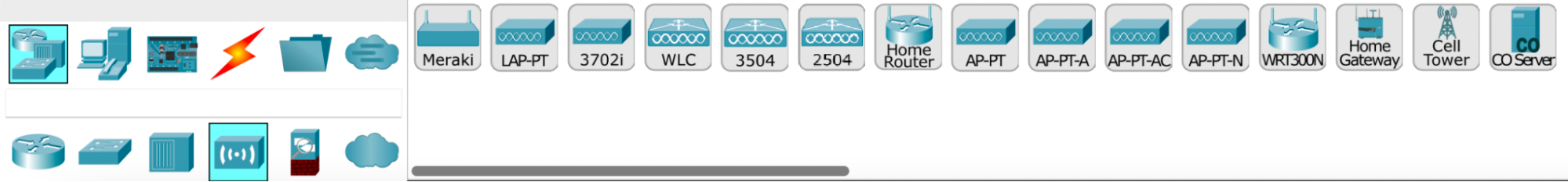
We’re going to look at three of these devices in particular:
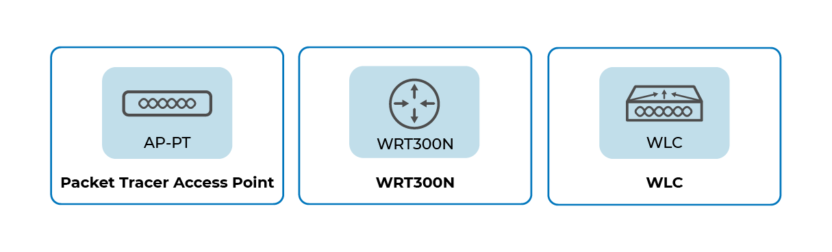
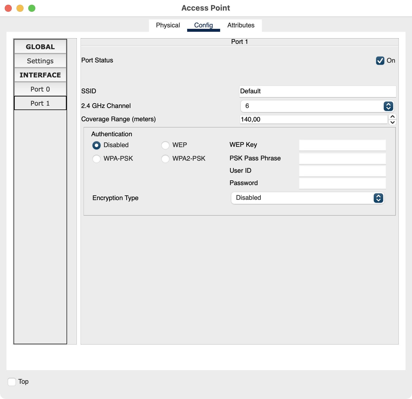
1. Access Point – Packet Tracer
This is an access point developed for Cisco Packet Tracer that doesn't actually exist in the real world. It’s very simple to use and does a great job—there’s no need to get bogged down with configuring more complicated wireless devices. It includes a basic Ethernet interface, but we can connect it to other interfaces, such as a fiber optic interface, which provides higher transmission speeds.
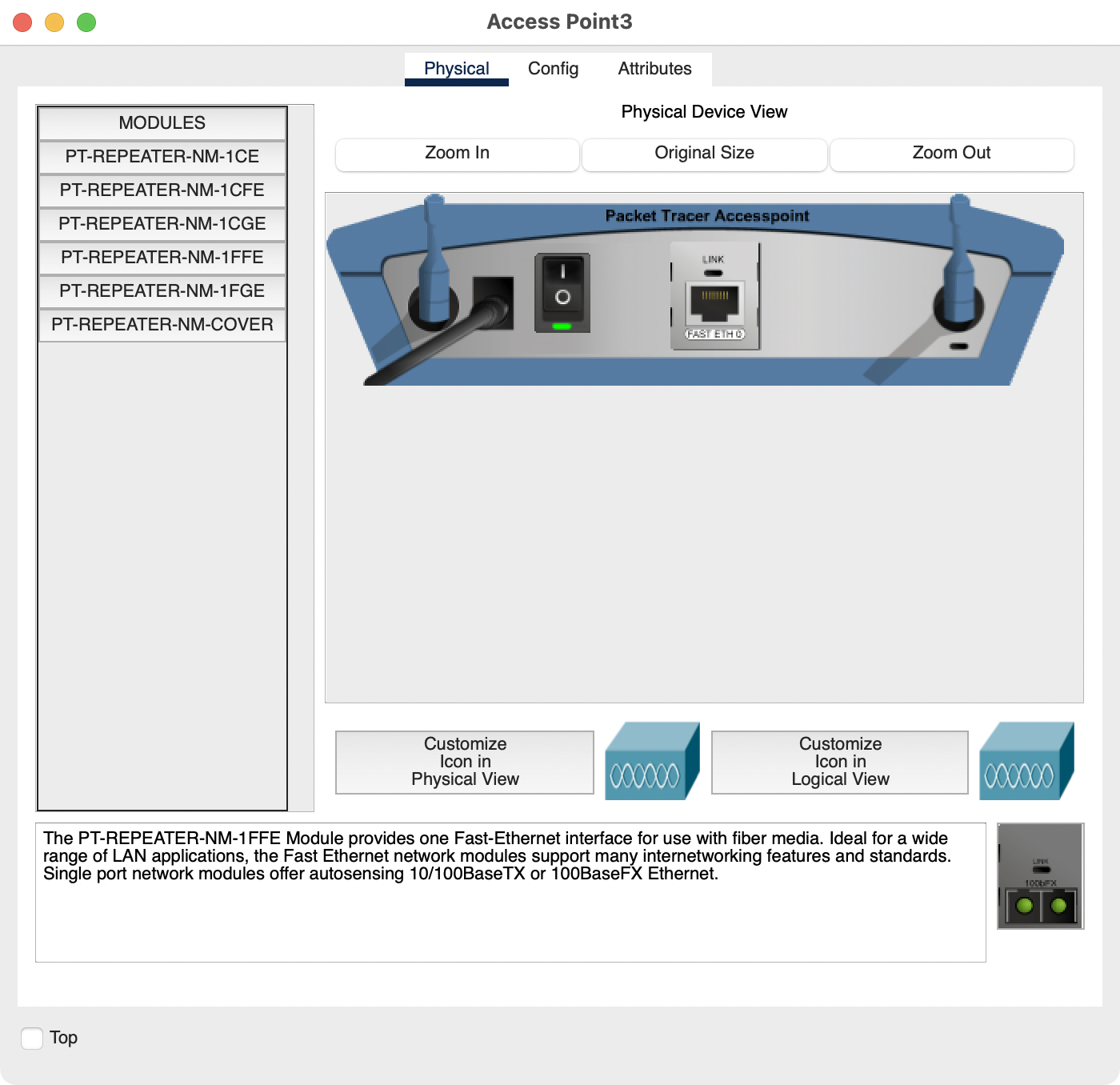
Configuring the device is quite simple. From the Config menu, you can configure basic parameters such as SSID name, wireless channel number, and wireless security.
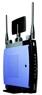
2. Linksys WRT-300N
The Linksys WRT-300N wireless router has more features than the Packet Tracer access point. This router is usually used in home networks (rather than corporate networks) because it has one Ethernet port for the Internet connection and four additional Ethernet ports to connect end devices in your home, such as computers or network printers. If you were producing a network diagram simulating a home network, this is the wireless router you’d choose!
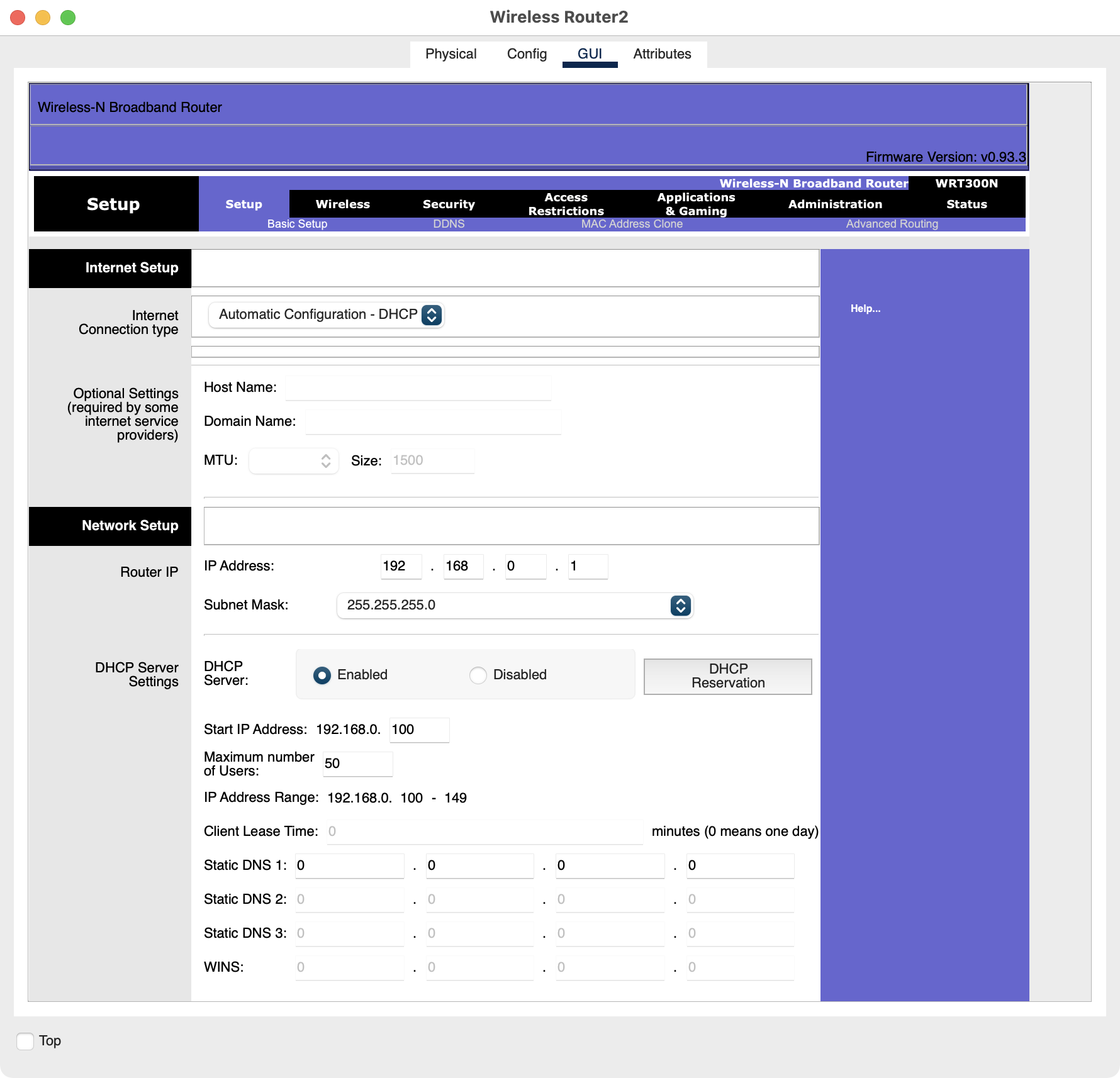
The Linksys WRT-300N router can be configured using the graphical user interface in Cisco Packet Tracer, exactly as you would if you were accessing the router using a web browser. All of the menus are clickable and provide access to the configuration pages. Great, isn't it?
The developers have tried to simulate real-life functionality for configuring the router.
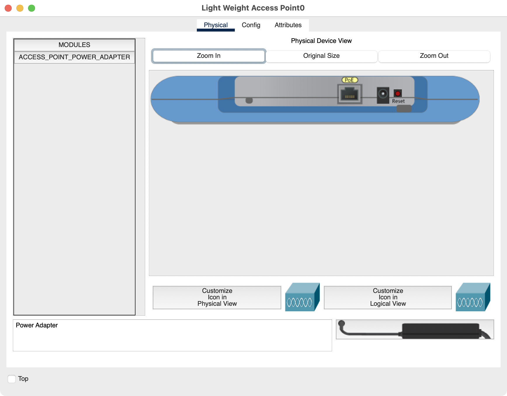
3. WLC – Wireless LAN Controller
The wireless access point and router that we’ve previously seen operate independently of each other. However, when you have various access points to manage in your organization, you’ll need to use a WLC (Wireless LAN Controller) to be able to configure the LAPs (Lightweight Access Point).
These lightweight access points don’t need any initial configuration and use the LWAPP protocol (Lightweight Access Point Protocol) to communicate with the wireless controller (WLC). The advantage is that each time an access point is added within the organization, there’s no configuration required, which is pretty handy!
Right, let's go back to Cisco Packet Tracer. We’re going to add the wireless access point. I’ll explain how to do this in the video below:
Add Mobile Devices
Now you're going to add mobile devices in Cisco Packet Tracer. Have a look at the end devices available in Cisco Packet Tracer. Go to the End Devices menu and choose End Devices.
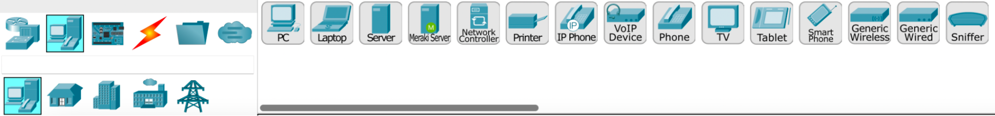
Choose the following wireless end devices:
Laptop
TV
Tablet
Smartphone
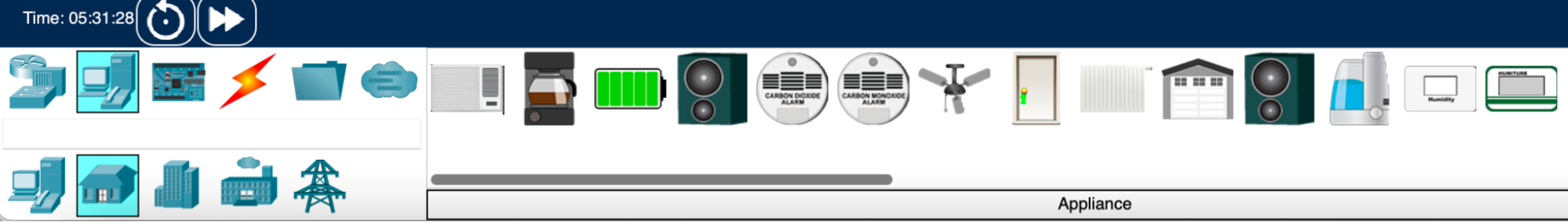
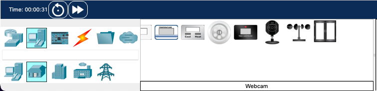
Oh no, there’s no IP camera! Don’t worry. I told you previously that the Cisco Packet Tracer developers thought of everything! Go to End Devices → Home:
Have a good look at the Home menu. You’ll find the webcam there. This has equivalent functionality to an IP camera and the configuration is very similar.
Let’s now add these end devices in Cisco Packet Tracer. I’ll explain how in this video:
Configure Your Wireless Network
Now that you’ve selected your wireless access point and added your wireless end devices, you need to configure them!
First of all, you need to choose an SSID name and wireless security with a passphrase. This is what you’re going to use:
SSID name | Wireless security | Passphrase |
Agency | WPA2-PSK | 1234-Metropolitan:1234 |
Next, you need to select the IP addresses, subnet mask, and default gateway to use for the wireless end devices. This is what you’re going to use:
Laptop | TV | Tablet | Smartphone |
192.168.60.1/24 | 192.168.60.2/24 | 192.168.60.3/24 | 192.168.60.4/24 |
IP camera | Gateway |
192.168.60.5/24 | 192.168.60.254 |
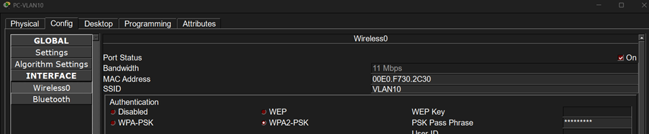
For now, configure the wireless network by specifying the SSID name and the wireless security. Here’s how to do it:
Next, we’ll configure the IP addresses of the wireless end devices. Watch the video and then do the configuration at your end:
Test the Wireless Communication Between Your Devices
All that’s left for you to do is to test the communication between your different wireless devices:
Configure Your Wi-Fi Network Using a Controller
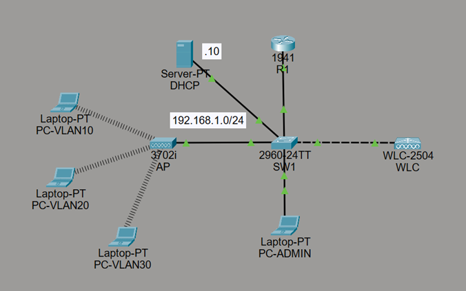
It’s also possible to configure your Wi-Fi network using a controller. Here is the topology used:

Router R1 uses a “Router on a Stick” configuration:
R1(config)#interface gig 0/0

R1(config-if)#no shutdown

R1(config-if)#exit

R1(config)#interface gig 0/0.1

R1(config-subif)#encapsulation dot1q 10

R1(config-subif)#ip address 192.168.10.254

R1(config-subif)#ip helper-address 192.168.1.10

R1(config-subif)#exit

R1(config)#interface gig 0/0.2

R1(config-subif)#encapsulation dot1q 20

R1(config-subif)#ip address 192.168.20.254

R1(config-subif)#ip helper-address 192.168.1.10

R1(config-subif)#exit

R1(config)#interface gig 0/0.3

R1(config-subif)#encapsulation dot1q 30

R1(config-subif)#ip address 192.168.30.254

R1(config-subif)#ip helper-address 192.168.1.10

R1(config-subif)#exit

R1(config)#interface gig 0/0.4

R1(config-subif)#encapsulation dot1q 1

R1(config-subif)#ip address 192.168.1.254

R1(config-subif)#exit
Switch SW1 uses the following configuration:
SW1(config)# vlan 10

SW1(config-vlan)# name VLAN10

SW1(config-vlan)# exit

SW1(config)# vlan 20

SW1(config-vlan)# name VLAN20

SW1(config-vlan)# exit

SW1(config)# vlan 30

SW1(config-vlan)# name VLAN30

SW1(config-vlan)# exit
The SW1 interfaces connected to R1, the Wi-Fi access point (AP), and the controller must be configured as TRUNK ports because traffic from all 3 VLANs (10, 20, and 30) needs to pass between the router, the access point that will broadcast one SSID per VLAN, and the controller.
SW1(config)# interface range fa 0/1-3

SW1(config-if-range)# switchport mode trunk
Here is the DHCP server configuration:
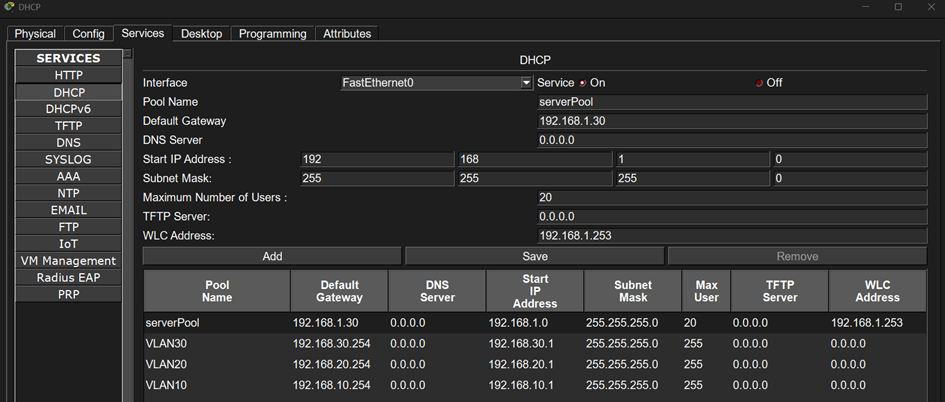
The DHCP server will also operate in VLAN 1, where both it and the Wi-Fi access points are located, in order to assign an IP address to each access point and provide the controller address for synchronization.
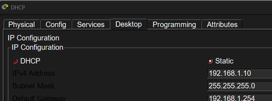
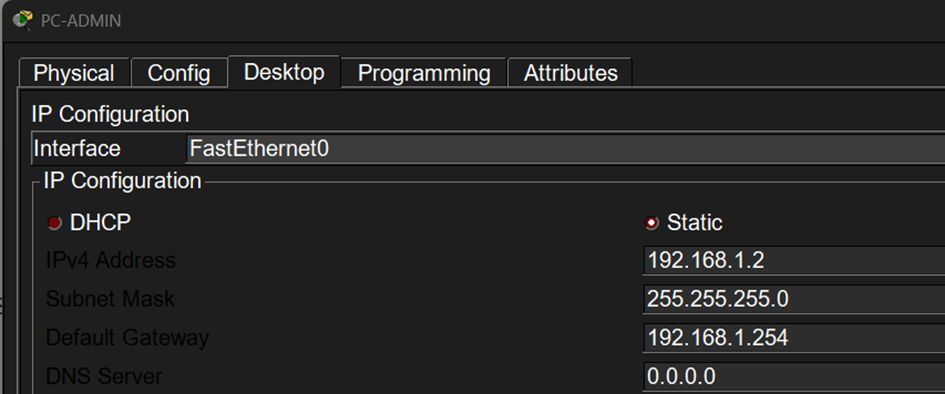
Here is the IP configuration of the admin PC that will be used to connect to the controller’s web interface:
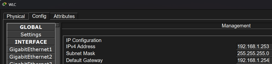
You then need to assign an IP address to the controller:
The next step is to connect to the controller from its web interface using the ADMIN PC’s browser:
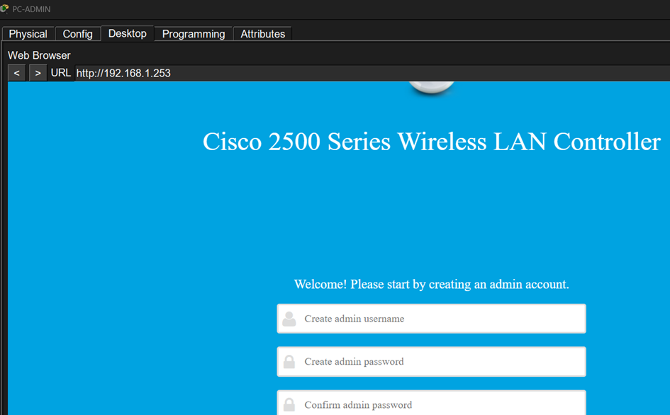
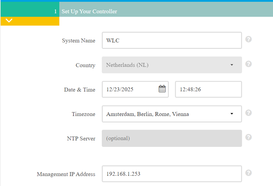
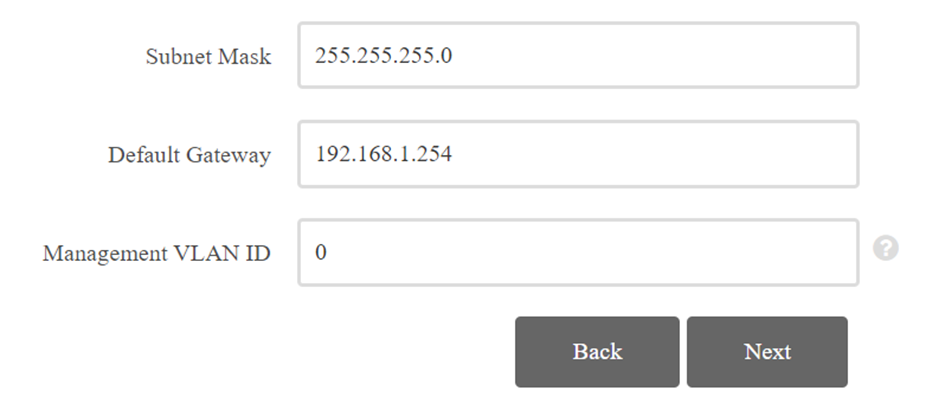
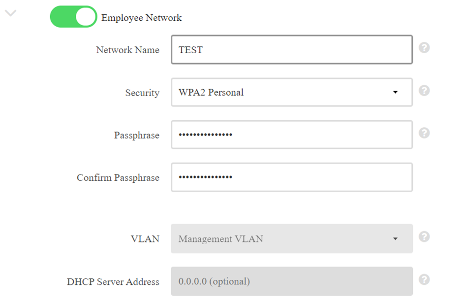
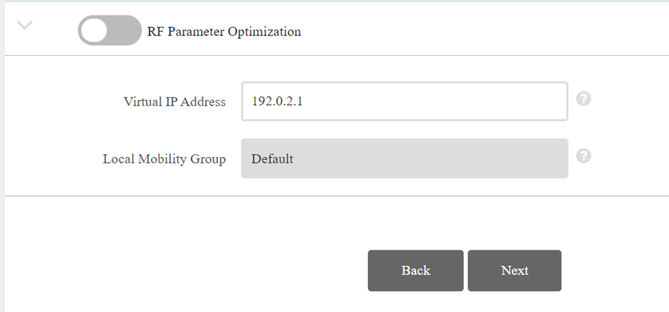
Here’s how to complete the controller’s basic setup:

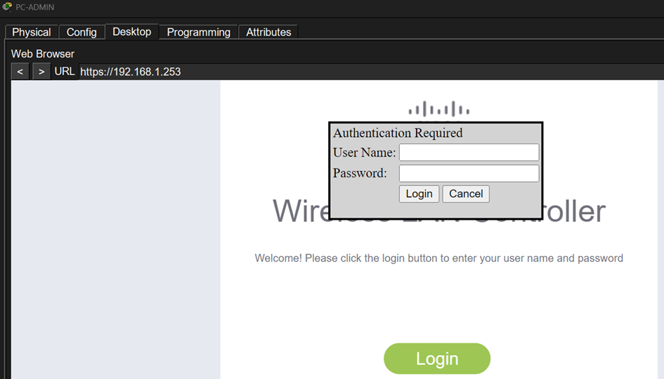
Once the setup is complete, connect to the controller over HTTPS and sign in:
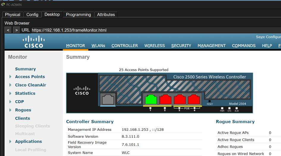
You’ll arrive at the controller’s main interface:
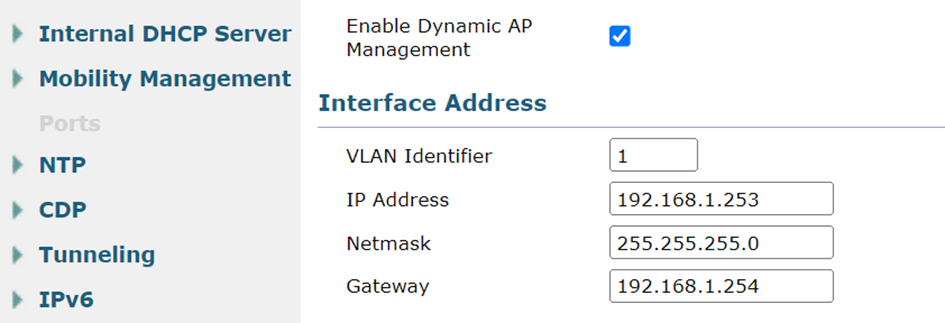
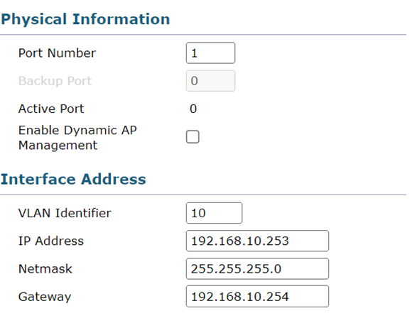
Go to the CONTROLLER tab, then INTERFACES, and modify the MANAGEMENT interface as follows:
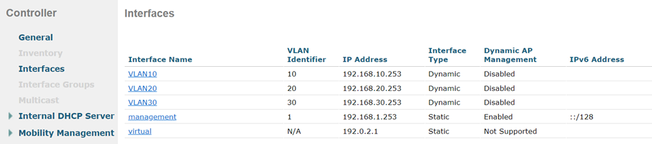
Once the interface has been modified, add one interface for each VLAN:

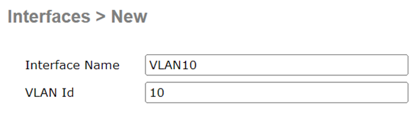
Do the same for VLANs 20 and 30. You’ll get the following result:
Then go to the WLANs tab and delete the TEST WLAN ID created during setup.
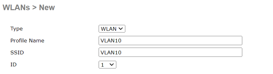
Add a new WLAN:
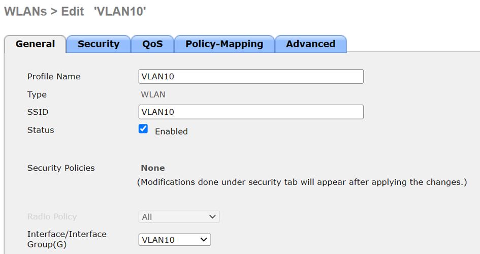
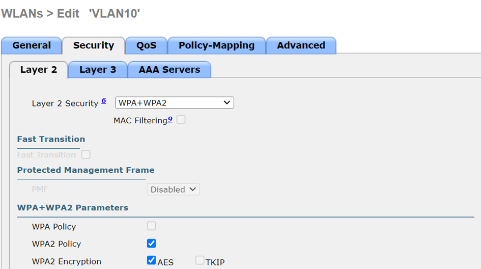
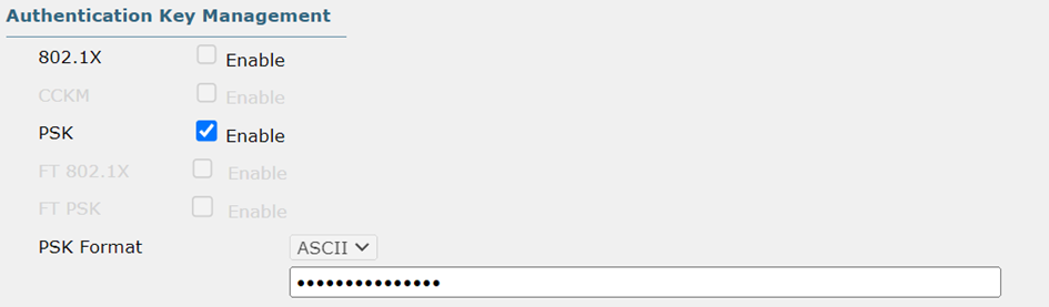
Once the WLAN has been created, configure it like this:
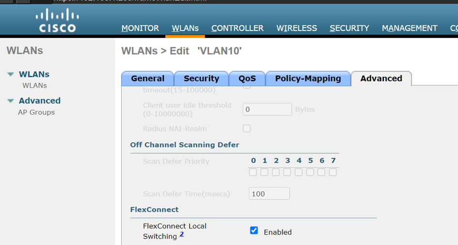
In the WLAN advanced settings, enable FLEX CONNECT LOCAL SWITCHING. This allows the access point to forward traffic between clients locally instead of sending it back up through the controller:
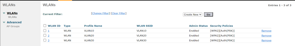
Configure the WLANs for VLANs 20 and 30 the same way, adapting the interface and the WLAN name (SSID). You should end up with 3 WLANs:
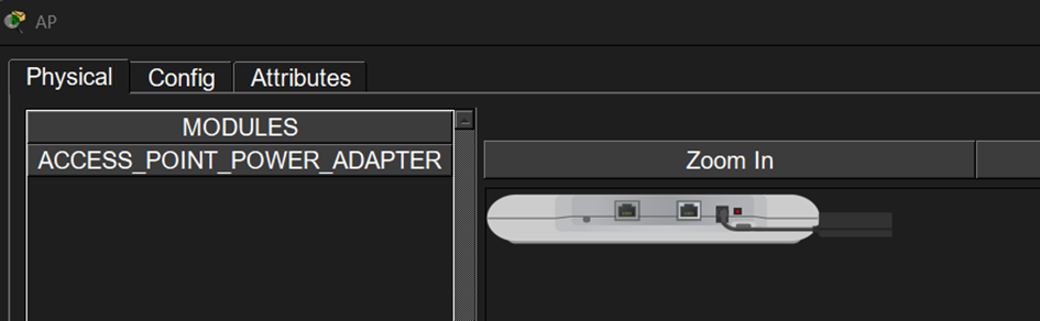
Install the power adapter on the Wi-Fi access point:
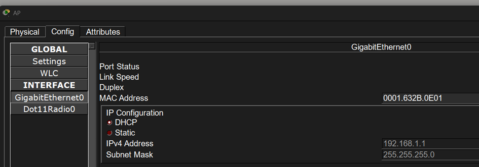
Then configure the access point to use DHCP:
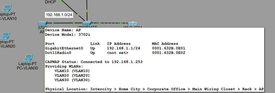
A few seconds later, hover your cursor over the Wi-Fi access point. You should see that it is correctly synchronized with the controller and broadcasting the different WLANs:
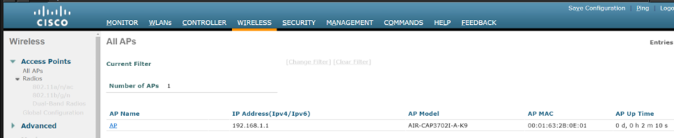
From the controller interface, you can see the access point under the WIRELESS tab:
Next, add a Wi-Fi card to each laptop. To do this, press the ON/OFF button on each PC. Then remove the Ethernet card by dragging and dropping it toward the Wi-Fi card icon at the bottom right:
The SLOT is now empty. Still using drag and drop, add the Wi-Fi card and press the PC’s ON/OFF button. Do the same for the other two PCs, then connect each PC to the SSID that matches its VLAN:
The three PCs are now connected!
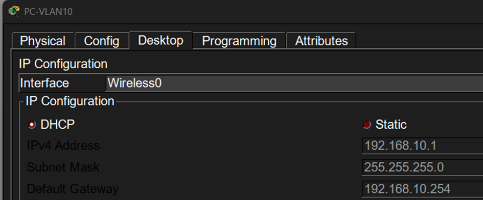
You can verify their IP settings. Here is the VLAN10 example:
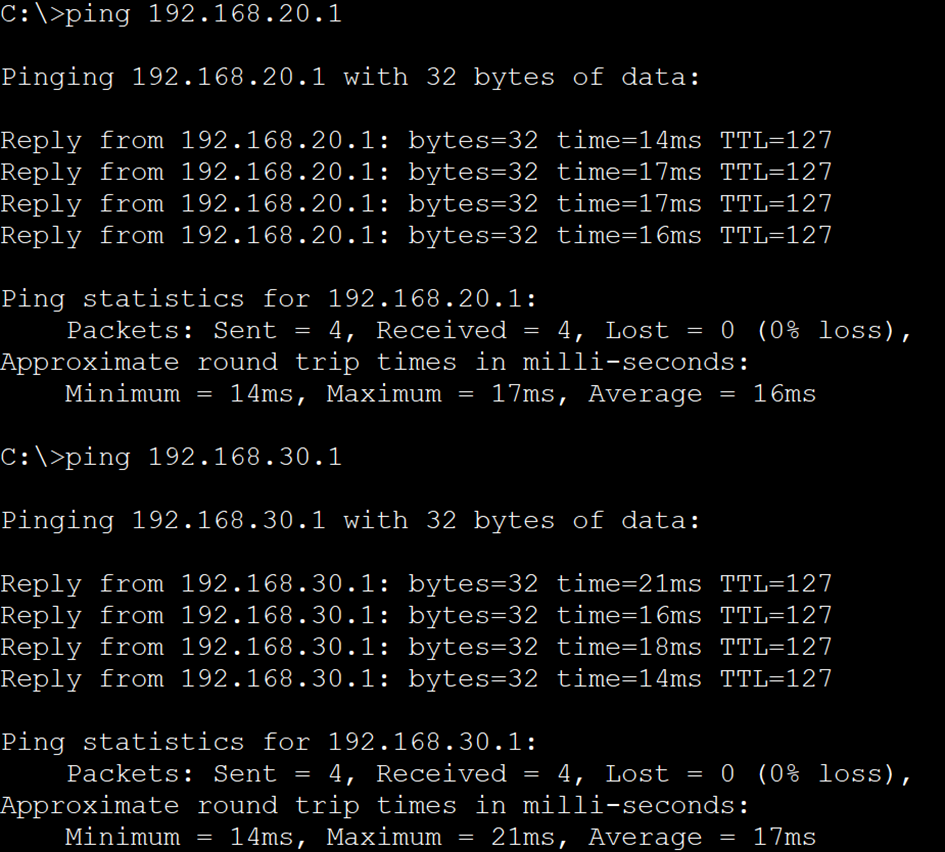
Because inter-VLAN routing is handled by R1, the PCs can communicate with each other:
Let's Recap!
In this chapter, you’ve seen:
how to choose a wireless access point based on your working environment.
how to add mobile devices to your network using Cisco Packet Tracer.
how to configure the wireless access point and IP configurations for wireless end devices using Cisco Packet Tracer.
how to test communication between the various end devices in Cisco Packet Tracer.
Configure your Wi-Fi network using a controller.
Now that you’ve configured a WiFi access point and the end devices, in the next chapter you’re going to configure the basic switch parameters.
