Discover How Networks Are Organized
Understand the Concept of a Network
Every day, you browse the internet, send and receive emails, or maybe log in to your favorite social network. But have you ever wondered how it all works?
For example, when you check your emails, you send a request (i.e., a message) to a device that stores the emails for you and many other users.
This device is often located hundreds or even thousands of miles away from where you are.
Before arriving at its destination, your message will pass through dozens of cables and devices, and will be converted, amplified, encrypted, attenuated, and more—it’s a real journey!
These steps are possible thanks to a huge global network, which enables connectivity between many different devices.
The purpose of networks is to allow the transmission of information. Before connectivity became commonplace, people would need to rely on physical media like floppy disks transported from one computer to another. Not very practical! :/
We now have a worldwide network called the internet at our fingertips. It is composed of millions of smaller networks, like those we will be creating together in this course.
It’s important to remember that there are different types of computer networks categorized by their size:
LAN (local area network)
A LAN is a network on a local scale, such as your home or company network.
MAN (metropolitan area network)
A MAN is a network deployed at a town or city scale. For example, these may be university networks that connect different faculties in the same city. They are made up of LANs, which together form a MAN.
WAN (wide area network)
A WAN is a network that is not tied to a single location. The most well-known of these is the internet, which is made up of MANs and LANs.
Identify the Physical Components of a Network
So what does a network actually look like? 🤨
The suspense is over - here’s a look at your very first network:
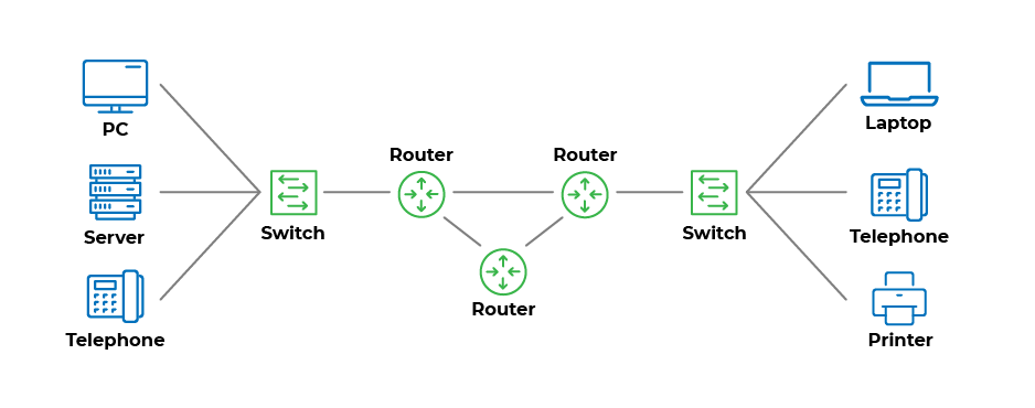
Beautiful, isn’t it? 
Here you have the complete architecture of a network, which is the components that make it up and how they’re organized and connected.
A logical diagram includes:
The network architecture.
Some aspects of its software configuration.
In the example above, the logical diagram shows a LAN (local area network). So let’s break it down into its different components:
You’ll find the end nodes at either end of the network: PCs, phones, servers, and printers. These components may need to exchange data with each other.
In the middle of the network, there are the intermediary nodes in green: switches and routers. These are at the heart of the network, as they link the different pieces of equipment to each other.
The lines between the different components represent the transmission media. These are cables or wireless connections that link two devices to each other.
Ok, now I understand what a network is made up of, but how is it all organized?
A computer network works like a road network.
When you commute to work, for example, you use different infrastructure:
You leave your house or apartment and head to the office.
You take a route made up of roads or highways.
You travel through intersections, junctions, and traffic circles.
Each of these parts of the road network has its equivalent in a computer network:
Your home and your office are the end nodes.
The junctions and traffic circles are the intermediary nodes.
The roads are the transmission media.
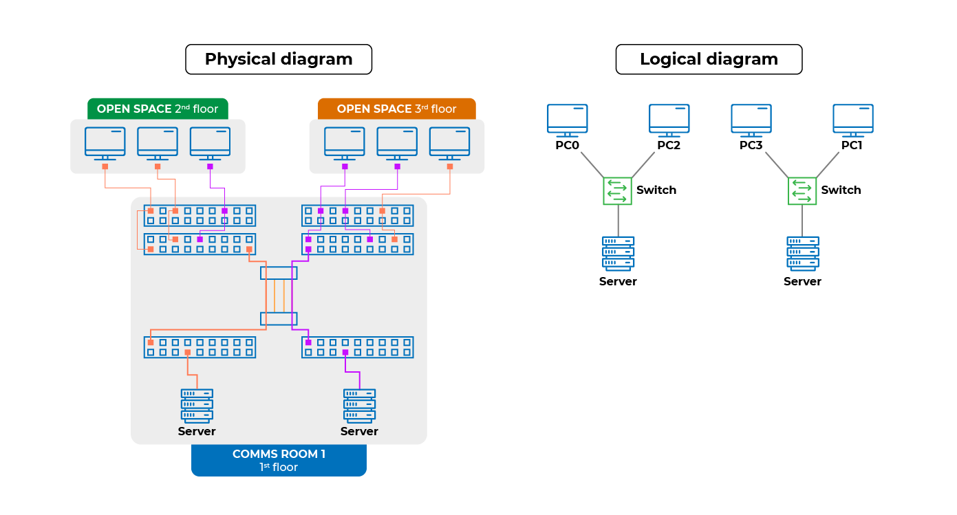
Differences Between Logical and Physical Diagrams
As a technician, you need to understand network diagrams.
Depending on the task you’re working on, you might come across two types of diagrams:
Logical diagrams - for designing, modeling, and configuring your network.
Physical diagrams - for deploying the network, installing, and cabling the equipment.
Physical diagrams provide other types of information:
The physical location of equipment (e.g., city/building/room).
The number of cables used to connect components.
The exact number of devices on the network.
A more detailed view of the intermediary devices.
They are also presented differently.
Discover Your First Task
Now you know the different components that make up a network, it’s time to get started on your first task!
You’ve just begun a new job at a digital services company specializing in network design. Your manager asks you to carry out some work for Tinos, a local driving school.
For the moment, the company consists of just one person: the director, Mr. Falman.
Your task is to connect his PC to a file server located on the company premises: a 20m² room on the same floor as the main office.
Mr. Falman has stressed that network security is his main concern.
To ensure you succeed in this first task, you decide to start by drawing up a network diagram. Next, your manager suggests you use a simulation tool.
A what?
We’ll be taking a closer look at how to use the simulation tool to create accurate network diagrams in the next chapter.
Let’s Recap!
Networks enable the exchange of data between different IT equipment.
Different types of networks vary in size, from private homes or business networks (LANs) to the internet (a WAN).
The physical structure is always made up of end nodes (PCs, servers, printers, etc.), intermediary nodes, and transmission media to connect the different components.
To make sense of complex network architecture, you should draw up a diagram.
There are two main types of network diagrams: logical diagrams to understand a network’s general architecture, and physical diagrams for carrying out installation and cabling operations.
Now you know the different parts of a computer network, let’s go to the next chapter to find out more about the simulation tool you’re going to use!
