Design more functionalities with UML
You've just implemented an enhanced functionality for your to-do list: marking a task as done! You may be getting lots of new ideas. What about setting a due date and checking whether you are on time? Why not assign the task to someone? As the complexity of your program grows, so does the need to communicate your ideas to other stakeholders: potential users, customers, coworkers, managers.
As beautiful as the English language may be, providing pages and pages of lengthy descriptions is not the optimal way of getting people on board with your ideas!
What about drawings?
Drawings are exactly what you need and it's what UML does for you: provide a globally understood, visual way of communicating ideas through diagrams.
There are lots of different types of UML diagrams, but for our purposes, we'll focus on two:
The use case diagram - this is designed to communicate who does what in your application.
The class diagram - this describes how use cases are translated into classes.
It's a little like what we did in the first chapter of this part, but more powerful! Let's check out how this can help organize and communicate any new features you may want to add to your application.
Visualize a use case diagram
Let's say you want to add more functionalities for tracking task completion and assigning tasks to your app. With functionalities like these, you could start to create a system that might be useful for whole teams, rather than just one person. For example:
A manager could define tasks, set a deadline, or assign employees to a task.
An employee could list tasks and mark them as done.
That's actually a lot of different information and interactions to track. This is where a use case diagram comes in handy. If you take your ideas listed above and put them in a use case diagram, it'd look something like this:
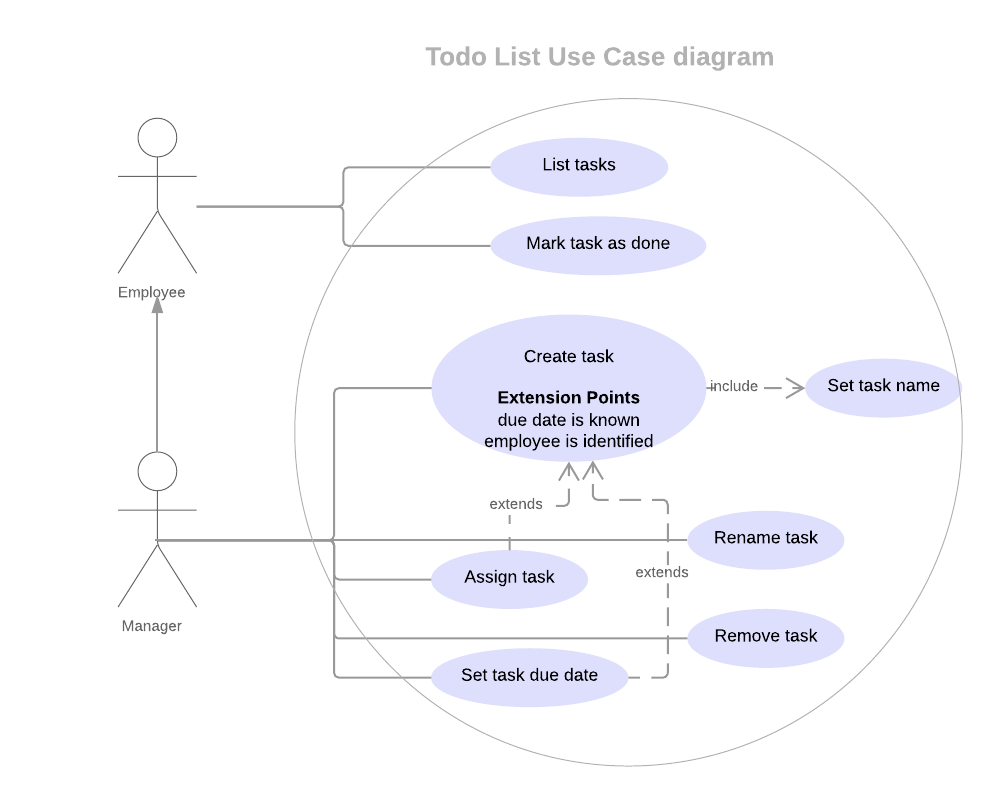
This diagram provides a visual representation of your needs. Let's break it down:
Actors
On the left hand-side you can see actors, which we've listed as "employee" and "manager." An actor is any external element interacting with the system. In this diagram, we have represented humans, but we could also have databases or web services represented as actors.Use cases
Inside the circle we have use cases. A use case represents a functionality that the system performs.
Association lines
Each line between an actor and a use case represents an association. It means an actor can perform the use case it is linked to.
Arrows
The arrow between manager and employee means that the manager is an employee. He inherits from the employee, which means he has access to all the use cases of an employee on top of him.Dotted arrows between use cases are called relationships.
In this diagram we have two of them:Extends means the use case can be triggered by another use case if a condition is met. We locate the triggering use case, then specify the condition inside it. The condition is called an extension point. For example, our triggering use case could be a manager creating a task. If the employee is identified (condition), the manager can decide to assign the task directly.
Include means the use case must be performed when another one is. For instance, when a manager creates a task (use case 1), he must set a name for it (use case 2).
Try it out for yourself!
Imagine you want to add a few more use cases:
Filtering by completed/current/overdue tasks.
Only displaying the tasks assigned to a given employee.
What would you add to the use case diagram? Think about:
What you want to do.
Who is supposed to do it.
The use case diagram is a way to remove any ambiguity associated with the initial wording of the functionalities you intend to develop. 🙂 Grab a pen and paper and see what you come up with!
Map out the implementation with class diagrams
Now that you are clear on the functionalities you want your system to perform, you need to map out how you plan to implement them. UML uses a class diagram to meet these needs. You can implement it in three types:
A simplified version representing the domain model, with class names and their associations
An extended version with the attributes that define the class
A complete version including the methods
You can see each version as a step towards a complete understanding of the structure of the system.
Step 1: model the entities and their relationships
The first version of your class diagram models the entities you need to manipulate and how they are associated. Those entities relate to the vocabulary the stakeholders use and map out the classes you will implement when you start coding.
In our case, the entities are the list and the task. Let's formalize how they are associated:
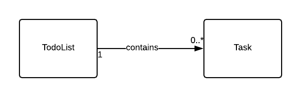
With a simple glance at this diagram, it's clear that:
You will be manipulating objects from two classes,
TodoListandTaskA to-do list can contain multiple tasks, while a task belongs to only one to-do-list.
Let's break this down. You can see that the diagram contains:
The classes are represented in a box.
The associations are represented by an arrow with a name and a multiplicity.
In our example, the name of the association is contains, which explains the intention behind the association: you're making it clear that the role of the to-do list is to hold tasks.
The multiplicity is given by the symbols at the edge of the arrow:
The 1 on the side of the
TodoListentity indicates that a task only belongs to one to-do list.The
0 .. *notation on the side of theTasksentity indicates two things. The first number indicates that atodoListcan be empty while the second start indicates that it can contain multiple tasks.
Now that we have mapped out the entities, let's define the attributes that will compose the state of each class to be implemented.
Step 2: define the attributes for each class
Let's look at the attributes that will compose each class. For a task, you definitely need a name, a due date, and the employee that will perform the task. For a to-do list, you need to store the list of tasks. You will also add an attribute called topic that will store the reason the to-do list was created in the first place. You don't want to mix groceries with your jobs tasks, do you?

In this second version of the class diagram, you can see each attribute associated to its class. For each attribute, the name of the attribute and its type are separated by the : character.
I only see the topic attribute inside the TodoList. Where is my list of tasks?
Good question. Since we are associating the the Task class with the TodoList class, the attribute is defined in the arrow that represents the association. Look how we specify the collection to be an ArrayList after the : character.
Finally, did you notice the - character before each attribute? This means each of them will be kept private. To access them, external classes will need to go through public methods. That's encapsulation. Now, let's define those methods!
Step 3: formalize the methods
In this last version of the class diagram, define the methods you want to implement. Each use case from your diagram must correspond to a public method.
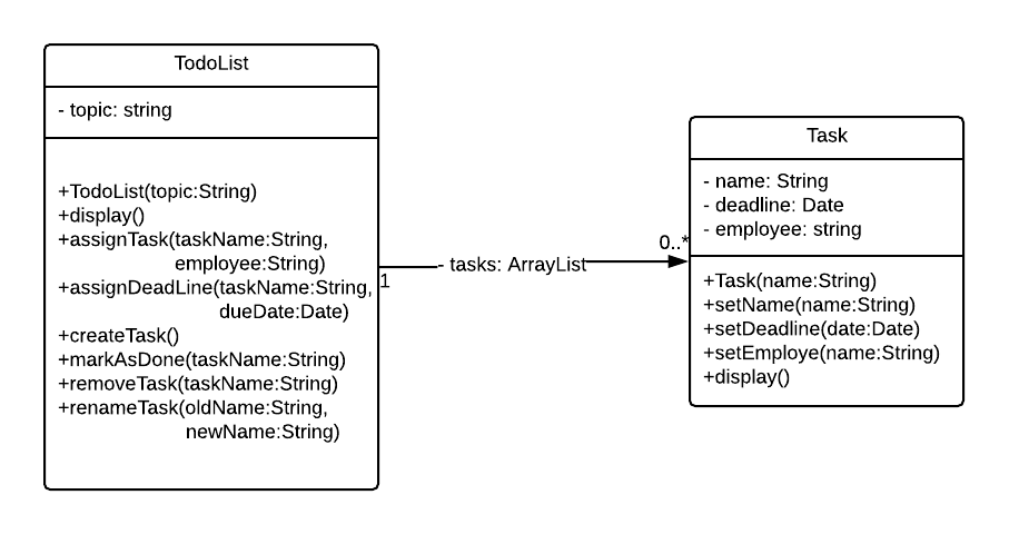
You can map out each use case with a defined method. Let's focus on a few of them:
TodoList(topic:String)is the constructor of the class. The topic is provided as an argument.display()displays the full content of the list! It takes no argument as it has access to everything it needs including thetopicattribute and the public methods of each objects of theTaskclass that thetaskslist will contain.createTasktakes no argument! However, you have seen from the use case diagram that you need a name. You may also want to define the due date and assign an employee.
Is there any other way to provide information or can it only be as an argument? 🤔
Yes, you can do it from inside the method by asking the user, communicating with a web service, or reading from a file.
In this class diagram, we have chosen to define only public classes. You are also free to add any support method to help keep the code as clean as possible! Those classes should not be made public since they are used internally and subject to change any time you need to refactor your code. You may choose to mark such a method as:
Private - if the support method is only needed in one class (identified in UML with the
-symbol).Package - if it intended to be used by several classes. Those methods will generally be included in a support class and made static to be used without creating an object. They are marked in UML with the
~symbol.
Summary
That's it for this small introduction to modeling with UML. You have seen that:
A use case diagram lets you map out the interactions between your system and its users.
A class diagram maps out the structure of the program in terms of class names and their associations as well as their attributes and methods.
While there are dozens of available diagrams, those two should suit most of your communication needs with the application stakeholders. At that point, it is not necessary for you to know how to write a diagram from scratch, but understanding them is really important.
It is now time to use all the skills you have gathered in this course. Let's move on to the activity where you will be implementing the system we just designed!
